In this post I have explained an innovative wireless LED brake light circuit which can be attached to a biker's helmet. The LEDs attached with the helmet circuit illuminates in response to the motorcycle braking generating an enhanced brake light effect from the user's helmet. The idea was requested by Mr. Bugoy.
Technical Specifications
Good day Sir! How are you? Yes, it was indeed a very interesting project. I am really an advocate of safety and security when it comes to my bike Sir. I wish you could see it soon. By the way, here are some links of an aftermarket product: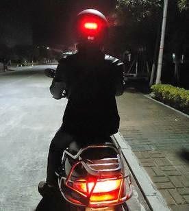
The Design
The proposed helmet brake light circuit could be easily implemented by using an inexpensive homemade FM transmitter and a small FM transistor radio.
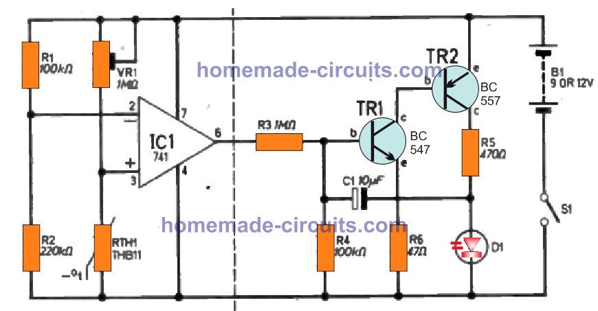
A small FM transmitter can be seen in the following diagram which becomes the brake light transmitter circuit for the helmet LEDs.
![]()
The above design represents a simple FM transmitter circuit which may be integrated with the brake light voltage signal of the motorcycle, or simply across the brake light lamp connection
The circuit generates an FM signal over the standard FM band of 80 to 108 MHz. Thus the transmitted signals become receivable over any standard FM radio placed within a radial distance of 30 meters.The coil would need tweaking for setting the exact point of reception over an FM radio
The indicated 12V lines are required to be connected directly across the brake light lamp of the bike.
The BC547 on the right along with its base zener ensures that the FM transmitter circuit receives the allotted 3 V for the operations.
The UM66 IC is a musical chip which enables the circuit to generate an AF modulated FM transmission ensuring much stronger and robust FM signals compared to a transmitter with no audio modulation stage.
Therefore each time brakes are applied, the transmitter is switched ON and sends a strong audio modulated FM signal for the FM radio positioned inside the helmet.
The FM Radio as the Receiver
Any small FM radio could be used for the purpose of receiving the transmitted signals from the above explained FM transmitter. An example circuit of a small FM radio may be seen below:
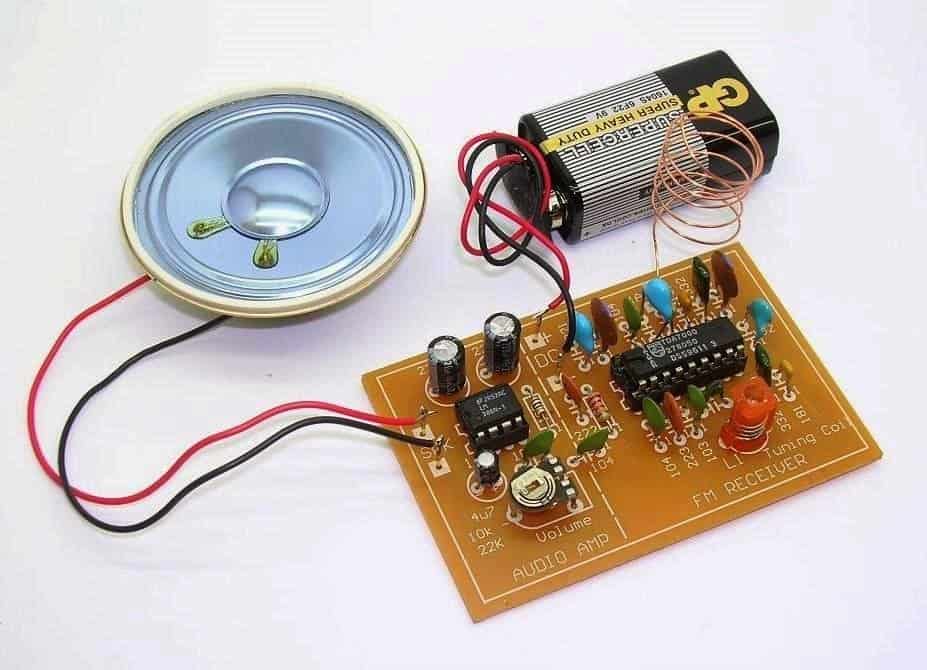
In the image we are able to see a speaker attached with the radio and also a 9 V battery as the supply source.
Both of the above mentioned attachments needs to be removed from the kit and should appear something as given below after the proposed modifications:
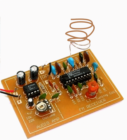
In order to make the above radio compatible with a LEd driver stage and for illuminating a set of LEDs in response to the received FM transmitter signals, we need to make some interesting electrical modifications with the shown FM radio kit.
The following figure shows how a small electrical stage consisting a BJT and inductor may be used for transforming the amplified audio from the radio into a DC which would then illuminate a set of LEds brightly each time the brakes are applied in the motor bike.
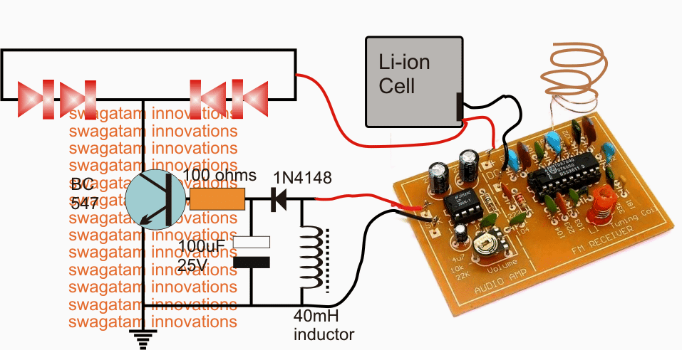
In the above diagram we see the speaker terminals of the FM radio being joined with an inductor and the output across the inductor further connected with a diode, capacitor rectifier stage for converting into a stable DC base drive for the following BC547 LED driver stage.
We can also see the 9 V battery being replaced with a 3.7 V Li-ion cell in order to make the design compact and easily inclosable inside the helmet.
When the radio begins receiving the switched audio, the weak audio frequency across the speaker wires become concentrated and boosted with the help of the connected inductor, this boosted voltage is rectified and filtered by the diode capacitor network so that the BC547 is able to receive a clean DC conversion for driving the set of LEds situated over the helmet body.
Now whenever the brakes are applied the signal from the transmitter is received by the FM radio inside the helmet resulting in the required illumination of the LED strip through the operations as explained in the above section.
How to set up the proposed LED helmet brake light circuit
Before installing the Rx LED module over the helmet, the radio board needs to be set appropriately as per the following explanation:
Switch ON the FM radio with no antenna connected and the station selection on the radio being on any random position.
You may find the LEDs glowing in this situation, now adjust the volume control preset in the amplifier section of the FM board very slowly until you find the LED just stops illuminating.
After the above setting disconnect the speaker output wires from the LED driver stage and let a speaker be connected with these wires. Also connect the antenna wire back in the shown position.
Switch ON the transmitter unit and adjust the red colored frequency coil or it could be a capacitor trimmer in other variants of FM receivers, tune it carefully until a clean and powerful musical audio (UM66 music) is detected in the speaker. Seal the tuning device with glue.
Now remove the speaker and connect the wires back with the LEd driver stage.
Switch ON the transmitter and you'll find the LEDs glowing brightly in response to the received musical transmission from the Tx unit. Switching of the Tx circuit should switch OFF the LEDs as well instantly confirming the perfect working of the system.
Check the response a few more times after which you may proceed with the final installations.


Questions & Answers
Hey Swagatam,
I am a sort of hobbyist and been working on wireless indicator system for my motorbike. so i need some help in connecting the wireless indicator system to my bike.
So what i did: opened the old RC Car, figure it out to grow the 2 LED strip (Red and blue brought it online) when press right and left separately. Same like the bike indicator.
Now the challenge i am facing is how to connect the right and left remote control switch to the bike indicator switch. Hope you get it what i am trying to say.
I'll grateful if you help to solve the problem. You can contact me @ kuntaldchowdhury@gmail.com
Hi Kuntal,
For a wireless turn signal system the wiring will need to be entirely independent, and noway associated with the bike's existing switches.
The transmitter switches will become the new turn signal switches, which will have no connection with the bike's existing wired switches.
the turn signal lamps will also need to be wired separately with the wireless receiver's relay contacts.
A 2-channel Tx/Rx unit could be used for the implementation
Sir..
Can u plzz help me I m making something.. But I cant find a suitable circuit for it..
I need something as smaal as possible.. It should be portable and main thing it can generate voltage as same as stun gun… I wll be glad if you can help me out..
Ujjwal, you can try the following circuit which is actually an inverter circuit and will generate 220V from a 12V battery source
https://www.homemade-circuits.com/2012/02/how-to-make-simplest-inverter-circuit.html
Hello Sir, Thanks for your post about DIY circuits. In this example of using FM transmitter/receiver for communicating with the helmet, if there are many users whose helmet's FM receivers are tuned to same frequency, then if one user applies brake , then all users' helmets will turn on. Is there any way to send unique signal for each user?
Hello RC, the above design is just for testing and hobby purpose, although this circuit too has the feature of a frequency adjustment so many 100s of unique sets could be produced using the above concept, however for a mass production one would have to employ a more advanced remote control modules.
Good Day Sir!
How will I connect the meter Sir? In amps or in volts? How is it exactly to monitor rate of discharge? Thank you Sir. I am so close to completing the project.
Bugoy, keep it connected as you have shown here:
s1284.photobucket.com/user/butchmillo/media/2015-01-06-1715_zps554c20bb.jpg.html
and monitor after how much time the 200mA drops to less than 50mA.
Sir, the amp reading for both battery and DC supply are almost the same Sir. More or less 200mA.
Bugoy, yes it's 200mA confirmed…keep the cell connected with the Tx and monitor the rate of discharge with the meter continuosly….
at 200mA a 800mAH cell shouldn't last more than 1/2 hour.
Sir, the AA battery does not get drained. I am using it for almost a month now for my testing. I even turned it ON for 1 hour straight. It is still working and reads 1.34volts.
Hello Sir!
Good Day!
I verified the current consumption using AA battery and it was also 200mA Sir. Below are some links for the picture of my measurements, both for battery and for LM7805 with 1N4148 diodes. The multimeter is set to 10A, so the reading 0.208 and 0.225 are in mA.
i1284.photobucket.com/albums/a561/butchmillo/2015-01-06-1713_zps5211ca6d.jpg
i1284.photobucket.com/albums/a561/butchmillo/2015-01-06-1715_zps554c20bb.jpg
Also, why is that an ordinary AA battery dont even get hot? What is the reason behind it Sir?
Sir, but even if the Tx is consuming 200mA, why is that a single AA battery could last long?
Hello Sir!
Is there a way to do that Sir? To lower the current consumption level? Because even the versatile LM317 gets hot so much.
Hello Bugoy, My suggestions are as per your readings which seem to be very contradictory, so it's a mystery to me how things are working.
If your AAA cell is not getting drained it means the Tx is not consuming much current through it….but if the 1.5V DC is applied from a 317 IC it's showing 200mA consumption…how can this happen??….whether it's from a 1.5cell or from any other source the current consumption will be the same always….it can't show different readings for a cell and for other DC sources.
Did you check the amp reading with a 1.5V cell, please check it and confirm if it's the same.
Or may be you are connecting the DC supply on some other points…connect the 1.5v from the 317 across the battery points or the connector points that's supposed to be for the cell fitting.
Hello Sir!
Happy New Year!
How are you? I finally came up with a more stable 12v to 1.5v converter. It goes like this. I used LM7805 and put 4 1N4007 in series with its output, cathode towards output. But the LM7805 and the diodes gets hot to the touch. Is there a way Sir to lessen the heat aside from using a heatsink? Thank you so much Sir.
Happy New Year to you too Bugoy!
Since your Tx is consuming 200mA current the involved devices will become slightly hot, there's no way to prevent it….unless the 200mA is reduced to much lower levels…
hello sir. Good day. I tested again last night, and found out that the Tx is using 205mA, both if using the emitter follower and a battery. I am sure that there is nothing wrong with the units sir, because they are both working well and they are brand new doorbells. The only thing is, it shorts any electronic power supply but still works.
Hello Bugoy, that answers everything, it means your Tx is very powerful and rated at 300mW which may have a range of more than 300 meters.
A BC547 is rated to handle at the most 100mA therefore it cannot be used in the emitter follower, you can try TIP122 and it will not heat up by much….or continue with the LM317 circuit.
Hello Sir!
Ok Sir, I will try your suggestions Sir. But it is really strange, because the Tx also makes my bench power supply shorted. The LED indicator on my bench power supply dims whenever I connect the Tx. Furthermore, I adjusted the LM317 to exactly 1.5V Sir. If I keep the 1k resistor in the emitter side, the voltage drops to only 0.6v Sir. So I omitted the 1k in the emitter side.
Hello Bugoy, such a thing can happen only if the load consumes excessive current, it means your Tx is consuming high amount of current….not sure why. In that case a 1.5V cell will also get drained within minutes.
Somewhere something may not be correct…can't troubleshoot without checking it practically.
Hello Sir!
Good day! I am sorry, I have a slight mistake in the diagram that I sent you. The 1k resistor should be on the collector side. Here are the revised diagrams. Thank you Sir. Even when using a voltage regulator circuit, it heats up the LM317.
i1284.photobucket.com/albums/a561/butchmillo/13_zps31e41f7f.jpg
i1284.photobucket.com/albums/a561/butchmillo/11_zps8baadac8.jpg
Hello Bugoy,
Your diagrams are perfect….however the results are very strange. A LM317 IC will not heat up if its output is adjusted according to the load voltage specs, here if you have adjusted the 317 output to 1.5V then it should not heat up, I can assure you that.
In the emitter follower design keep the 1K resistor on the emitter side and check the response….you may also try increasing the value of the base 10K to 47K or 100K and see if the transistor still heats up.
Hello Sir!
Yes sir, I am sure the supply is 12V. I measured it with my multimeter. Here are some pictures again sir for your reference. Why is that it also makes the LM317 (voltage regulator circuit) heats up so badly? Thank you Sir again for your unending patience.
i1284.photobucket.com/albums/a561/butchmillo/10_zpsab4e93ed.jpg
i1284.photobucket.com/albums/a561/butchmillo/11_zps8baadac8.jpg
Sir, here are some pictures of the Tx and I edited the underside to show you what I did with the emitter follower. Please refer to it, maybe you can have a better understanding Sir. Thank you, thank you so much.
i1284.photobucket.com/albums/a561/butchmillo/1_zps80fe0483.jpg
i1284.photobucket.com/albums/a561/butchmillo/2_zpsfbee8646.jpg
Yes the diagram and the connections are correct….do one thing increase the base resistor of the transistor to 33k or above and check the response, also if possible show me through a drawing or image how you have practically connected the BC547 pins…
Hello Sir! I tried connecting a 100 ohm and 1k resistor to the collector of the BC547. The BC547 dont heat up that much, but the resistor does. It heats up that I cant even touch it.
Hello Bugoy, 1K will not heat up even if it's connected directly across the 12V terminals, are you sure the input is 12V…or is it 24V??
Hello Sir!
How are you? I found out something. The Tx really makes everything shorted. I used the 7805 and it heats up. I used the adjustable voltage regulator LM317 and it also heats up. But still the Tx works well. Its just that it becomes shorted when connected to power. But when I use a AA battery, it does not heat up. Why is that Sir? The Tx makes every electronic power supply shorted. I bought another unit, and the result is the same. So I assume that there is nothing wrong with the Tx. What to do now Sir? Thank you so much.
Hello Bugoy, connect your Tx directly through a 1K resistor to the 12V supply and check the response, it seems it has a built in 1.5V zener diode.
but even if it has a 1.5V zener, the emitter follower circuit should not heat up because its output voltage is also at the same level that is at 1.5V….something is doubtful in your proceedings, can't trace it.
The Tx diagram shown in the above article already includes an emitter follower so you can refer to it for the details.
first try the Tx with a 1K resistor….
Hello Sir!
Can you please provide a schematic for that "emitter follower" circuit. Maybe I just misunderstood your instructions. Thank you Sir. The Tx works great using 1.5v AA battery. But if I use the "emitter follower", the BC547's collector heats up rapidly.
Hello Bugoy, you can see an example circuit in the following article:
https://www.homemade-circuits.com/2012/08/simplest-dc-cell-phone-charger-circuit.html
here cell phone is being fed the charging volatge through a emitter follower BJT.
The 9V zener clamps the emitter voltage to 9V.
hello sir. Merry christmas. I am already on the final stage of our project. But we still have the same small problem. The bc547 collector is still heating up after a couple of minutes. It also affects the wire itself that goes to the motorcycle brake light supply. Have you tried doing the circuit sir and supplied 12-14v? Notice the collector, it really heats up. I used several bc547 but still the same. Thank you.
..Merry Christmas to you too!!
hello Bugoy, I have tried such "emitter follower" circuits on many occasions, it will burn only if the load is faulty or short circuit, check your transmitter circuit separately with a 1.5V cell.
Alternatively, you can also try using a 7805 IC with 6nos 1N4007 diodes in series at its (+) output for getting 1.5V for the Tx.
Hello Sir!
How are you? Just got busy from work these past days. Anyway, an update regarding our project Sir. LED strips are not advisable due to its 12v rating. I tried wiring up only 3 of them but still it wont light up. So i custom-made a 4-LED strip made of recycled and junk parts. I will send some pictures next time Sir. But now I have a small problem. The BC547 that was added to the transmitter gets hot after about a couple of minutes of continuous activation. Why is that Sir? What if I need to press the brakes longer that 2 minutes? I'm afraid I might burn something. Thank you.
Hello Bugoy, that should not happen, because the Tx would be consuming only a few mA current…….check with another transistor, there could be something wrong with the transistor or its pin configuration.
If it still happens, try connecting a 100 ohm resistor in series with the emitter of the transistor.
Hello Sir!
Yes, it was indeed 1.8v across base and ground. When I added a 1k resistor across emitter and ground, it measured 1.3v. Thank you Sir. Now, I am on the process of thinking how to build the LED strip or housing for the helmet. Any suggestion Sir? Considering the helmet has a spherical shape and not flat. Thank you so much.
nowadays LED strips and ribbons have become very popular you can make use of them, a small section of these strip or ribbon can be tried.
Hello Bugoy, it can be assembled over a flexible plastic strip, but first first it's important to check whether the circuits are responding as per the required specs or not.
hello sir. I made the circuit on a breadboard. Unfortunately, its output is 3.5v sir. I supplied 14v from my power supply. What to do sir? Thank you.
Hello Bugoy, check the base voltage of the transistor, the emitter voltage will be equal to the base voltage, with three diodes the base voltage should be around 1.8V….also,, connect a load 1K resistor across the emitter and ground of the transistor and check again….3.5V could be due to absence of any load.
Hello Sir!
Good Day!
Thank you for the suggestion. I will be buying the parts today. Is that for 12v supply only Sir? The bike is generating 14-15v when running. And the brake is only used when running. Will the circuit be sufficient enough for 14-15v supply? Thank you sir.
Hello Bugoy,
The suggestion will work for 14-15V inputs also, before connecting the output to the Tx, first confirm whether the emitter of the BC547 is producing the required 1.5/1.8V approximately…once confirmed you may proceed with the integrations
hello sir! Good day. I finally got it working sir. I used the other test point but with a slight delay. Is there a way to eliminate that delay sir? By the way sir, how am i going to convert the Tx to be used with the motorcycle's 12-14v supply? It only uses one AA battery (1.5v). Thank you in advance sir. Take care.
….also remember to connect the negative of the Tx with the bike's negative.
Hello Bugoy, try to locate a nearby capacitor that may be responsible for this delay. you can simply remove it for preventing the delay effect.
for the Tx you can do the following…take a BC547 connect its emitter with the positive of the Tx circuit, collector with the motorcycle brake light positive signal.
connect the base with the above brake positive through a 10k resistor…..and connect the 3 series 1N4148 diodes across base and ground….cathodes towards ground
the above will allow the Tx to get the required 1.5V only from the bike's 12V supply
Good Day Sir!
My assessment is that, the 2.1v supply is not fully saturating the transistor to fully switch it that is why the LEDs are not in full brightness. But if I reduce the number of diodes, the LEDs are lighting up a small amount. I used 4 1N4148 to fully OFF the LEDs when not activated. Three or less makes the LEDs light up a little bit. What to do Sir? Thank you.
Hello Bugoy, I think either you'll have to trace out some other well defined signal point in the circuit or use an opamp circuit for the present signal source, because sensing a difference of 0.3V may not be feasible using a transistor circuit
Hello Sir!
Good Day!
The diode fix worked Sir. But there is again another small problem. Before, without adding the diodes (1N4148), the LED stays ON even when Tx is OFF. Now that I added four (4) diodes in series with the transistor's base, the LED finally turned OFF when not in use. But the problem is, when Tx is activated, the LED does not attain full brightness. It responds perfectly but not so bright. I think less than half the full brightness. Why is it like that Sir? Does is has something to do with the addition of diodes? I tried removing some but the LED will illuminate if I use 3 or less diodes. Thank you so much Sir.
Hello Sir!
The 4.5v DC supply responds perfectly to the switching transistor circuit that you provided. The only downside is that it has a half second delay when turning OFF. Still, the 2.1v supply is the best, but I later found out that it does not respond to the multimeter when set to VDC. It does not fully turn OFF (zero volt) when deactivated. It has a reading of 2.1v when OFF and 2.37v when ON. And later found out that it responds better to the multimeter when set to VAC. From 0.47mVAC when OFF, to 1.5VAC when ON. What do I do now Sir? The transistor switch circuit does not respond to that set-up. Thank you so much. I really want to make use of that point (2.1v supply) because it perfectly responds even to the slightest and fastest pressing and depressing of the Tx.
…sorry my above suggestion is incorrect, try using two or three 1N4148 diodes in series with the base of the transistor…this might just work
Hello Bugoy, just try adding a capacitor in series with the transistor base….any capacitor will do, 1uF, 10uF or any other value….positive will go to the 2.1V signal.
hello sir! Good day! I already did the circuit. But there was a little problem. The 2.1v dc supply is not responding. I found out that it did not make a zero volt when Tx is release. It stays in 2.1v output. It only increases a few mV when Tx is pressed. And i found out also that the 2.1v dc is actually AC. I set my multimeter to vAC and it reads 47mVAC when OFF and becomes 1.5 vAC when ON. Whereas when the multimeter is set to vDC, it reads 2.10 vDC when OFF and 2.37 vDC when ON. Thank you in advance sir for your unending help.
i almost forgot sir, you only mentioned to ignore the capacitor and the coil. How about the 1N4148 diode sir? Do i need to include it or not? Thank you very much sir.
the diode may also be eliminated…it's not required.
hello sir! Thank you so much. The 4 Ni-Cd cells only has 1.2v each sir. Having a total of 4.5-4.8v. But the Rx only requires 3v alkaline batteries. Would it damage the circuit? Do i have to use mobile phone Li-ion cell that has 3.7v instead? I will be working on it now sir.
Hello Bugoy, you can use the N-Cd cells, but for 4.5V make sure the LEDs have around 220 ohm series resistors with each string, or you may include one more LED in the string, that is use 3 LEDs in each string with no series resistors
Hello Sir!
Good Day!
What do I do now Sir? Now that I found two points with RF outputs? What point will I use? The one with 4.5v supply but with OFF delay, or the one with 2.1v supply but perfectly sync? Thank you so much Sir.
hello sir! Good day! How are you? I worked on it this past weekend and im happy to get results. I found two points. But both have downsides. The 1st one illuminates the LED fully (i measured it at 4.5v which is exactly the same as the supply voltage), but has more than half a second delay when turning OFF. It stays ON for more than half second before turning OFF after releasing the transmitter. The 2nd one barely illuminates the LED only 1/4 the brightness (i measured it at 2.1v), but responds in sync with the transmitter's ON and OFF. By the way, i used 4 pcs Ni-Cd rechargeable batteries. What do i do now sir? Thank you very much.
….previously you mentioned 3V for the Rx, how come you are using 4 cells in series, that would produce 6V??
Good day Bogoy, use the 2.1V trigger for the application.
Assemble the transistor LED stage that's shown in the last diagram above.
Use 1K resistor instead of the shown 100 ohm, do not use any coil or capacitor ignore those components.
Connect the 1K end with the 2.1V supply, connect the emitter of the transistor to the 3V negative and LED anodes to the 3V positive….and check the response.
Hello Sir!
Thank you so much Sir. So that is the only way to find the correct point? I will do that now Sir. By the way Sir, will this test damage the circuit if I connect to a wrong or particular point? Thank you so much Sir. I will update you later when I have the result.
Hello Bugoy, the 1k resistor will prevent anything from getting damaged…connect the cathode of the LED with 1K and the 1K end to the negative of the battery….after this you can use the anode of the LED for investigating the required point in the circuit.
Hello Sir!
Good Day!
I opened up already the wireless doorbell unit. I want to show you what's inside. So you could guide me better on how to start. The unit has an LED on the receiver unit and flashes according to the tone generated. There are 36 different tones and can be selected by a tact switch. The problem is, where can I get a supply where it turns ON when the transmitter is pressed and turns OFF when released? The set-up of the doorbell is that it finishes the tone while flashing the LED even if the transmitter is depressed. And it take a few seconds to do so, giving a delay or prolonging of the action which is supposed to be OFF when transmitter is depressed. There is no tone option for one-time, one-shot switching. Also, how many LED can it power up? The transmitter requires 1.5v (one AA battery) while the receiver requires 3v (two AA batteries). I am hoping you could help me out with this Sir.
Below are some pictures for your reference Sir. Thank you so much.
i1284.photobucket.com/albums/a561/butchmillo/2014-11-27-1636_zps35722a72.jpg
i1284.photobucket.com/albums/a561/butchmillo/2014-11-27-1637_zps840319bf.jpg
i1284.photobucket.com/albums/a561/butchmillo/2014-11-27-1639_zps76228d59.jpg
i1284.photobucket.com/albums/a561/butchmillo/2014-11-27-1640_zps6b62677d.jpg
i1284.photobucket.com/albums/a561/butchmillo/2014-11-27-1641_zps2a752c58.jpg
i1284.photobucket.com/albums/a561/butchmillo/2014-11-27-1643_zps58b1e3d8.jpg
That's great Bugoy! The LED which is switching ON only momentarily will have a circuit controlling it….try to locate the input to this stage…this input will be directly linked with the Tx ON/OFF periods, so we can use this input for illuminating the brake light LEDs through a BJT buffer stage.
so please try to locate this input signal….you can check this by connecting a LED/1k resistor string across the different points with respect to the ground until the correct point is found.
Hello Sir!
Good Day!
I'm so happy! I have some good news for you Sir. Earlier, when I went to the city, I accidentally found a shop that sells battery operated wireless doorbells. There are 4 units left and I need to have one of those before its totally gone. can we make use of it sir for the wireless helmet brake light? Will it be easy to modify the unit for the desired purpose? I hope you could help me with it. Thank you so much Sir. Take care.
Hello Bugoy,
A remote door bell circuit can be effectively used for the above purpose. Whether it's easy or not will depend on the hobbyists experience, you can try it out… but I cannot guarantee success.
Hello Sir!
Good day!
How are you? I guess my enthusiasm came back after two failed attempts (though the first one, the isolated power supply, is not actually a failure because it worked. It just wont work
with the capacitive proximity sensor alarm). I tried building the stun gun featured in your blog but still I cant make it work. Maybe because I could not find exact parts like the audio transformer and the 10nF mylar caps.
…you can make use of an automobile ignition coil for trial purpose
Hello Bugoy, the transformer is the vital component, if you don't make it correctly you won't get the specified ersults.
for getting higher voltage you may have to select a higher primary/secondary turn ratio, such as 20:10,000, the 20 turns should be made by using thicker wire may be a 0.6mm while the 10,000 turns could be 6 times thinner that's 0.1mm thick……use a ferrite EE assembly for the winding.
Hello Sir!
Good Day!
Are there any stun gun circuit that you can suggest for me? When I was doing the isoalted power supply, I found out that the secondary's output is I think 300V dc but with a very low current. Can that be amplified to reach a decent few thousand volts? Im sorry, but I cant make the stun gun, you featured in your blog, work. Thank you so much Sir.
that's great Bugoy, keep up the good work!
Hello Sir!
Good Day!
I think another failure again. I cant make it Sir, I'm sorry. Maybe RF projects are not my line. I still do not have the proper and necessary know-how to do it. Also, the scarcity of parts is another problem. I am sorry to disappoint you Sir. Maybe I would think of a simple project instead. The projects that I learned from your blog are really amazing. I still use them now. Some are for household, while some are for my beloved motorcycle.
Hello Bugoy,
Don't worry, keep trying and be hopeful, because failures are often followed by success….keep it up!
Good Day Sir! How are you? It was a very sad and frustrating day for me. I could not find anywhere the UM66 chip. No store sells it here Sir. What should I do? Thank you.
Hello Bugoy, you can make a transistor astable frequency generator or a 555 frequency generator and use it in place of UM66….first make sure it produces an audible sound around 2khz to 6khz frequency by testing it separately and then join it with the Tx circuit..
Hello Sir!
Good day! Thank you for the information Sir. I will be finding such coil. Because I think there is no available ferrite core small enough to fit the application. I will be updating you asap. Thank you so much.
Good Day Sir!
How are you? I have one more question Sir. How am I going to make the 40mH inductor? The electronic stores here do not sell inductors. Thank you so much Sir. Take care.
…i meant buzzer coil…
Bugoy, you can make it home by winding the thinnest possible magnet wire around any ferrite core, about 500 turns, I had used a buzzer as the inductor in my circuit as shown in the below example:
1.bp.blogspot.com/-j-B5fWFwJVo/UQTewNIMC7I/AAAAAAAACzA/Y7WLCNIbUGs/s1600/buzzer%20coil.jpg
Good !dea. Keep on working….
thanks
Hello Sir!
Good Day! How are you? I was trying to make the circuit work but I cannot make it as steady as possible. It seems the tuned frequency varies and keeps on changing. Sometimes it works, sometimes it does not. What could be wrong Sir? Thank you. I am sorry I just messaged you now, Just got busy from work. Take care.
Hello Bugoy, did you include the UM66 or any musical chip with the transmitter input?
without an audio modulation the reception will not be accurate….I have tested this design and for me it worked flawlessly.
Hello Sir!
I already completed the parts/components. I just got home. I will be starting the project tomorrow. Please wish me luck. Take care.
Sure Bugoy, i wish you all the best, I am sure you'll succeed
Good Day Sir!
Thank you for your input Sir. I will be gathering the parts tomorrow. I hope to get them all. Any small cheap Fm radio will do Sir? How many LED can it drive Sir? A cellphone battery could be a power supply for the receiver, isn't it Sir? Thank you so much Sir. I will update you ASAP. Take care Sir.
Hello Bugoy, yes any small FM radio capable of driving a small speaker will do the job.
around 4 bright red LEDs can be lit from such radios.
Hello Sir!
Good day! No Sir, I just want to make two units. for me and for my riding buddy, my best friend. He is so good to me and I owe him a lot, so I think giving him something unique is worthwhile. So if I will but a cheap FM radio, would you help me hack it to suite the application Sir? I do not have much knowledge in RF. Maybe I will just send you a picture of the actual circuit of the FM radio so that you could guide me correctly. Thank you so much Sir for your patience.
Hello Bugoy, for just two units it will never be a problem, just set the two units on different FM bands isolated far apart.
The FM radio must have the facility or the power of driving a a small speaker…then it would be perfectly compatible for this project.
Hello Sir!
How are you? Its been so long. I was busy working on our project (wireless helmet brake light) but I do not know what to do next. Where can I find a circuit for that FM radio that you mentioned here? Also, if the antenna is cut to a shorter length, will it shorten also the transmission range? So that even if two riders are using it, it will not interfere with the other. Thank you Sir. Please keep me posted. Take care.
Hello Bugoy,
FM radio is perhaps the most basic of all the other modules…if you cannot get this then I am afraid it would be difficult for you to complete this project.
yes, the length of the antenna directly decides the sensitivity of the Tx, Rx units.
moreover the modules will need to be aligned or set over a suitable spot across the FM band and this spot will be unique to each of the modules, so cross connection is anyway less likely across adjacent bikes if any, are you planning to manufacture these units?
Dear Sir
I am Making a project there will a cable car it will go a side to another Side I want
A Circuit Wich can Change Dc Motor Ploarity After 1 minute
dear cycle, make the following circuit:
https://www.homemade-circuits.com/2014/10/power-switch-on-alarm-with-auto-off.html
select "C" to get 1 minute ON on power switch ON…use a DPDT relay instead of the shown SPDT and wire the relay with the motor as shown in the following example circuit (see only the contact connections):
https://www.homemade-circuits.com/2014/09/automatic-pwm-door-openclose-controller.html
Sir please Help Me
Can You Plz Give me a circuit that can change the polarity After 1 minute. Plz sir give me that circuit its my Happy New Year Project
Cycle, please explain the requirement with more details
Thanks…
as you can see that vout feeds positive voltage to positive terminal but i was confused as to what line feeds the negative voltage to negative terminal then it occured to me that negative voltage is actually a 0 voltage so perhaps that negative terminal does not need to be feeded by any circuit line is it ?
Hello Gururaj, all the "earth" or the zero line shown in the image will become a common line by getting interconnected and then this common line will become the negative line for the circuit.
Ofcourse the circuit will have its own negative which will need to be connected with the above explained common negative line,
without the negative and the positive connected the circuit will fail to function.
picpaste.com/Battery-eliminator-schematic-aUyXgHr5.jpeg
Hello Mr.Swagatham,
Thanks for your prompt reply.
Sorry i was late as i was not able to reply as i was facing problem acessing blogger.This is the schematic i was mentioned which you can see in the link.
Hello Mr.Swagatham,
I was always fascinated by electronics and easy schematics posted by you has motivated me to make a foray into the world of electronic hobbyist but i understand that to drive circuits i would need a good psu so i checked some schematics for transformer psu one of which caught my interest which i intend to build but its output stage has set me confused, Can you please help me ? How do i share its schematic with you as i dont have google drive or can i post a link to its image ?
Hello Gururaj,
yes you can post the image in any free image hosting site and provide me with the link.
Hi, yes the scr based grid tie inverter looks very interesting, especially the last one in the following article:
https://www.homemade-circuits.com/2014/04/simplest-grid-tie-inverter-gti-circuit.html
You can try it using smaller transformers such as a 1amp transformer and without connecting the output to the grid initially….it's important to confirm the SCr operation first before going for the final set up.