In this post I have explained a simple PWM controlled automatic turnstile or door circuit featuring an automatic open/close action via a photo-interrupter stage. The idea was requested by Mr. Bruce Clark.
Technical Specifications
Thank you for a really fantastic service you provide.
Would you please be so kind as to help me with a modification of the your circuit at:
I would like to use an arduino PWM to control a 12Vdc gate control motor ( will draw 9amps at startup) using MJ11015G power transistors.
My dilemma lies in the requirements to supply sufficient power to the transistors base and the associated circuit modifications within the limitations of the arduino Uno. It is my very limited understanding that the inverting gates would not be even nearly sufficient for this application.
I know that the limit of the Arduino is 40mA per output pin. If I were to apply a PWM output through a 120 Ohm resistor directly to the base of these transistors would I be okay? If not please advise an alternative.
Basically, I wish to use the motor for a turnstile or automatic door and as such need the dead stop and reverse functionality. A photointerrupter will be used to determine position of door and induce a brief halt and then reversal to initial position where it will be indexed via a sensor.
The door can be rather heavy and space is very limited so I plan to drive the door using the motor mentioned through a reduction gearbox.
Your help would be most sincerely appreciated
Kind regards
Bruce Clark
The Design
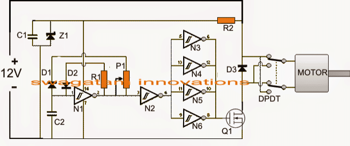
A very simple PWM based motor control circuit with high torque and instant stop/reversal feature can be witnessed in the given diagram and may be used for operating the proposed turnstile or automatic door application.
The PWM Schematic
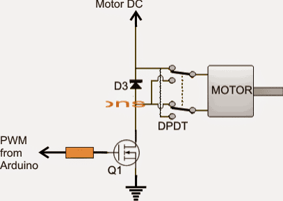
If an Arduino based PWM is intended to be used, the IC stage in the above diagram could be removed and the PWM from the Arduino could be applied directly at the base of the mosfet via a 10 ohm resistor as shown below
The Relay Driver DPDT
Parts List
R1 = 10K
R2 = 47 OHMS
P1 = 100K POT
D1, D2 = 1N4148
D3 = MUR1560
C1,C2 = 0.1uF/100V
Z1 = 15V, 1/2 WATT
Q1 = IRF540
N1---N6 = IC MM74C14
DPDT = DPST SWITCH OR DPDT RELAY
Circuit Operation
The first circuit above, which is not using an Arduino input is configured around 6 hex-inverter Schmidt NOT gates from the IC MM74C14, where N1 forms the fundamental rectangular wave pulse generator, N2 is used for detecting the duty cycle of the pulses generated by N1 via the pot P1, while the remaining gates are wired as buffers.
P1 is used for determining the speed at which the door is supposed to open and close automatically.
The final PWM output achieved from the outputs of the buffers N3 to N6 is applied to a driver mosfet Q1 which becomes responsible for controlling the speed of the attached motor depending upon the fed PWM data.
A DPDT switch can be seen rigged with the motor terminals and the mosfet, this switch is used for acquiring an instant braking and reversal of motor rotation.
The good thing about this circuit is that it does depend on a H-bridge driver configuration for achieving the motor flipping actions, rather the same is implemented by the use of an ordinary DPDT switch.
As per the request, for executing the automatic door opening and closing via photo sensitive device, the DPDT could be replaced with a DPDT relay and the coil of this relay could be in turn controlled through the intended photo sensitive device (photo-interrupter) such as a photo diode or an LDR.
The photo interrupter stage will be updated soon.

Questions & Answers
I have a push down lever style door and when I push the handle down and unlatch the door, I would like to have a sensor that triggers an automatic door opener. Then set the closer for 5 seconds to relatch. The electromechanical opener/closer would be a simple gate opener at 110
I think the following concept should work to fulfil your requirement:
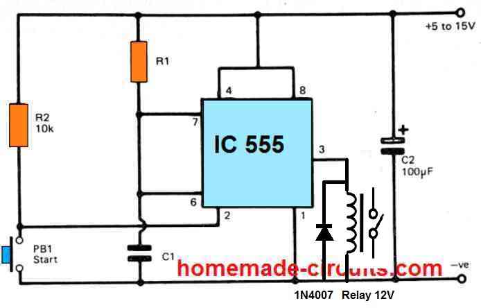
The relay contacts can be configured with the door opener system, and the push button can be configured with the mechanical handle, so that each it is pushed, it presses the push button in turn, and activates the relay for a specific duration, as set by the values of C1, and R1…
hand clapping window curtain open circuits
Do I need to use aurduino pwm?? is aurduino pwm and aurduino r3 same?
Arduino is not required here, the PWM is created using the N1 stage