• Skip to main content
  • Skip to primary sidebar

Homemade Circuit Projects

Need circuit help? Post them in the comments! I've answered over 50,000!

Blog | Categories | About | Contact | Calculators-online
You are here: Home / Security and Alarm / Power Switch ON Alarm with Auto OFF Circuit
circuit simulator image

Power Switch ON Alarm with Auto OFF Circuit

Last Updated on July 6, 2019 by Swagatam 17 Comments

In this post I have explained a simple monostable based power switch ON alarm circuit which automatically switches OFF after an adjustable preset delay. The idea was requested by Mr. Will Boswell.

Table of Contents
  • Technical Specifications
  • The Design
  • Circuit Diagram

Technical Specifications

Hi there, my name is Will Boswell. I am currently working on a project that involves adding an alarm sounder to an existing circuit, I shall try and explain as best possible.

The existing system is a warning light system whereby when the high voltage kit that I use is turned on, red beacon lights flash in order to warn those inside and outside of the testing area. These lights operate at 24V.

I would like to put a sounder in that sounds for 5 - 10 seconds when the system is turned on, in addition to the lights.

I was rather hoping that I would be able to just piggyback off of one of these lights for my supply but after my own research I have begun to get rather lost and it is a few years since I was at college!

So in a short summary, I am looking for some assistance in regards to having an alarm sound for 5 - 10 seconds every time the system is turned on / lights are activate.

Please any questions, just ask!

Many Thanks in advance

The Design

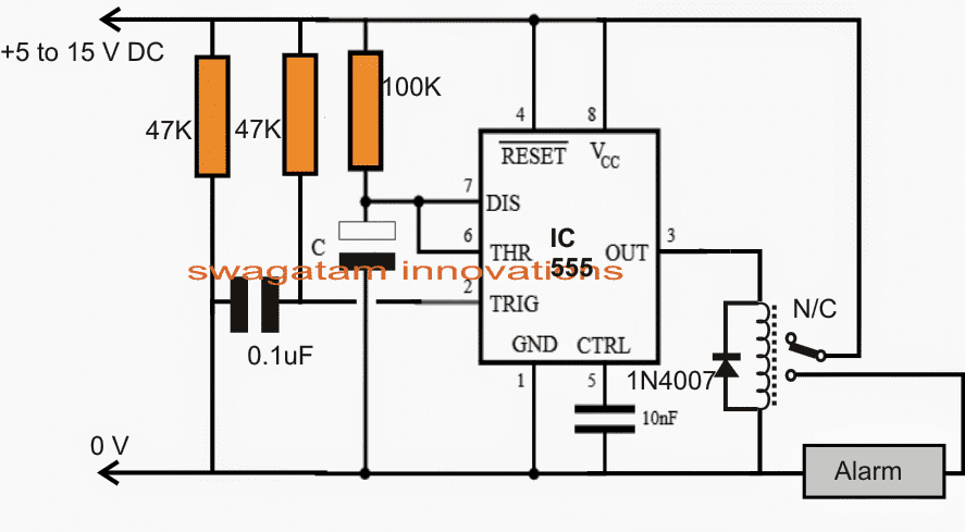
The requested power switch ON alarm circuit using a delay OFF circuit may be witnessed in the given diagram.

It's basically built around a standard IC 555 monostable multivibrator configuration. The operations are rather simple:

When power is switched on across the circuit, the 0.1uF capacitor momentarily grounds pin2 of the IC, sending an instantaneous triggering signal to the 555 monostable.

This immediately prompts the output of the IC to go high causing a toggling voltage to be activated for the attached relay.

The relay switches ON itself and the alarm unit connected with its N/O and the pole.

The alarm begins buzzing only until the relay shuts off automatically due to the featured monostable one shot characteristic of the IC 555.

The ON period of the relay or the IC output is determined by the values of the 100kresistor and caapcitor C. Different values for C may be tried in between 10uF and 100uF for achieving the closest possible duration of 5 to 10 seconds.

Circuit Diagram
warning message: electricity is dangerous, proceed with caution
monostable2Balarm2Bcircuit


You'll also like:

  • 1.  Gadgets to Protect Women from Assaults and Harassment
  • 2.  Laser Activated GSM Call Alert Security Circuit
  • 3.  AC 220V Over Current Monitor and Cut OFF Circuit
  • 4.  Simple Motorcycle Security Alarm Circuit
  • 5.  Security Alarm Circuit using RCWL-0516 Microwave Radar Sensor
  • 6.  Loop-Alarm Circuits – Closed-Loop, Parallel-Loop, Series/Parallel-Loop

Filed Under: Security and Alarm Tagged With: Alarm, Auto, OFF, ON, Power, Switch

About Swagatam

I am an electronics engineer and doing practical hands-on work from more than 15 years now. Building real circuits, testing them and also making PCB layouts by myself. I really love doing all these things like inventing something new, designing electronics and also helping other people like hobby guys who want to make their own cool circuits at home.

And that is the main reason why I started this website homemade-circuits.com, to share different types of circuit ideas..

If you are having any kind of doubt or question related to circuits then just write down your question in the comment box below, I am like always checking, so I guarantee I will reply you for sure!

Previous Post: « How to Make a Solar Panel Optimizer Circuit
Next Post: Digital Up/Down Volume Control Circuit »

Reader Interactions

Comments

  1. Dr.Sison says

    July 4, 2023 at 9:00 am

    Hi Swagatham…greetings
    Can i incorperate the above to water level indicator circuit with 4049 ic output stage?

    Reply
    • Swagatam says

      July 4, 2023 at 9:12 am

      Hi Dr, Sison, you can use this circuit with your water level indicator outputs, but how will you integrate the 4049 outputs with this circuit?? You will need to add a BC547 transistor with this circuit for it to work.

      Reply
  2. Theuns says

    December 4, 2017 at 10:18 pm

    Hi there does this circuit: https://www.homemade-circuits.com/power-switch-on-alarm-with-auto-off/ reset when power is removed?

    Awesome website!!

    Reply
    • Swagatam says

      December 5, 2017 at 9:40 am

      Thanks Theuns, yes the circuit will reset each time power is switched OFF

      Reply
      • Theuns says

        December 9, 2017 at 6:15 pm

        Thank you for getting back to me. Forgive my ignorance as I am a mechanical guy, but I have built this circuit and can’t get it to work. Must the 0.1uf capacitor be of the ceramic type or can electrolytic also work? And capacitor C – can it be made bigger to achieve 30sec to 1 minute time?

        Reply
        • Swagatam says

          December 9, 2017 at 8:42 pm

          The capacitor can be any type…however please try with a higher value such as a 1uF or a 4.7uF, or a 10uF….the lead which is going to the ground line should be the negative lead of the capacitor…please try this your circuit will surely start working….if still not let me know…

          the values of C and the 100k can be dimesioned as preferred by you for getting longer start ON delays.

          Reply
          • Theuns says

            March 31, 2018 at 12:36 am

            Thanks Swagatam – I finally got to this circuit today: it works well. Thanks again for an excellent website!!

            Reply
            • Swagatam says

              March 31, 2018 at 8:36 am

              You are welcome Theuns, I am glad you coold make it successfully….

              Reply
  3. Agus Riyadi says

    November 19, 2015 at 2:35 pm

    i like this web

    Reply
  4. sharoj alhasan says

    October 18, 2014 at 5:51 pm

    Dear sir

    I am Making a project. Wich is like Cable card At the card there will write Happy New Year

    The Card will Go each side to another Side

    I Want a Circuit wich can change Polarity after 1 minute

    Reply
    • Swagatam says

      October 19, 2014 at 12:43 pm

      I have already answered your question with appropriate links, please check your previous comments.

      Reply
  5. Cyrustech says

    October 11, 2014 at 9:04 pm

    I luv this site

    Reply
    • Swagatam says

      October 12, 2014 at 12:38 pm

      thanks!

      Reply
  6. suresh aprs says

    October 5, 2014 at 12:34 pm

    Thanks for your quick reply. Sir, I already completed this circuit.in this circuit not having phase revers protection and no low , high voltage protection.pls help me.
    Mail: aprssuresh@gmail.com

    Reply
    • Swagatam says

      October 5, 2014 at 2:01 pm

      If possible… I'll try to design them and publish in this blog soon.

      Reply
  7. suresh aprs says

    October 4, 2014 at 3:08 pm

    Sir,
    Im using three phase motor, some time one phase fail. I want three phase preventer with time delay out put and phase revers , low voltage, high voltage detector. Please help me.
    Mail ID: aprssuresh@gmail.com

    Regards
    Suresh

    Reply
    • Swagatam says

      October 5, 2014 at 9:03 am

      Suresh, you can try the following circuit which is a single phase preventer circuit only, without high, low cut off….make this first if it works as per the requirement, we can later on add the high/low cut off in it.

      easy-electronic-circuits.blogspot.in/2013/08/simplest-single-phase-preventor-circuit.html

      Reply

Need Help? Please Leave a Comment! We value your input—Kindly keep it relevant to the above topic! Cancel reply

Your email address will not be published. Required fields are marked *

Primary Sidebar


Subscribe to New Posts

Categories

  • Arduino Projects (89)
  • Audio and Amplifier Projects (132)
  • Automation Projects (17)
  • Automobile Electronics (101)
  • Battery Charger Circuits (83)
  • Datasheets and Components (104)
  • Electronics Theory (143)
  • Free Energy (37)
  • Games and Sports Projects (11)
  • Grid and 3-Phase (19)
  • Health related Projects (25)
  • Home Electrical Circuits (12)
  • Indicator Circuits (14)
  • Inverter Circuits (88)
  • Lamps and Lights (142)
  • Meters and Testers (69)
  • Mini Projects (46)
  • Motor Controller (64)
  • Oscillator Circuits (27)
  • Pets and Pests (15)
  • Power Supply Circuits (108)
  • Remote Control Circuits (50)
  • Security and Alarm (64)
  • Sensors and Detectors (101)
  • Solar Controller Circuits (59)
  • Temperature Controllers (42)
  • Timer and Delay Relay (49)
  • Transmitter Circuits (29)
  • Voltage Control and Protection (39)
  • Water Controller (36)


Other Links

  • Privacy Policy
  • Cookie Policy
  • Disclaimer
  • Copyright
  • Videos
  • Sitemap


People also Search

555 Circuits | 741 Circuits | LM324 Circuits | LM338 Circuits | 4017 Circuits | Ultrasonic Projects | SMPS Projects | Christmas Projects | MOSFETs | Radio Circuits | Laser Circuits | PIR Projects |

Social Profiles

  • Twitter
  • YouTube
  • Instagram
  • Pinterest
  • My Facebook-Page
  • Quora
  • Stack Exchange
  • Linkedin


  • Recent Comments

    • Swagatam on Simple Delay Timer Circuits Explained
    • Swagatam on How Shunt Regulator TL431 Works, Datasheet, Application
    • Swagatam on How to Design Simple LED Driver Circuits
    • Swagatam on How to Design Simple LED Driver Circuits
    • SA on How Shunt Regulator TL431 Works, Datasheet, Application

    © 2025 · Swagatam Innovations