• Skip to main content
  • Skip to primary sidebar

Homemade Circuit Projects

Need circuit help? Post them in the comments! I've answered over 50,000!

Blog | Categories | About | Contact | Calculators-online
You are here: Home / Remote Control Circuits / Whistle Activated Switch Circuit

Whistle Activated Switch Circuit

Last Updated on January 2, 2024 by Swagatam Leave a Comment

In this post I have explained how to build a simple whistle sound operated relay circuit, which can be used for switching ON/OFF a 220 V load through whistle sounds.

Table of Contents
  • Circuit Description
  • Parts List
  • Advantages
  • Disadvantages

You can consider this circuit to be a whistle operated remote control circuit which will operate a connected load remotely through the sound of whistling.

Circuit Description

The whistle frequency is captured by electret-type microphone MIC1 and sent to transistor Q1 for amplification. The signal is amplified by transistor Q1 and is fed to the input of IC1, which is an LM567 PLL (phase-locked-loop) tone-decoding integrated circuit.
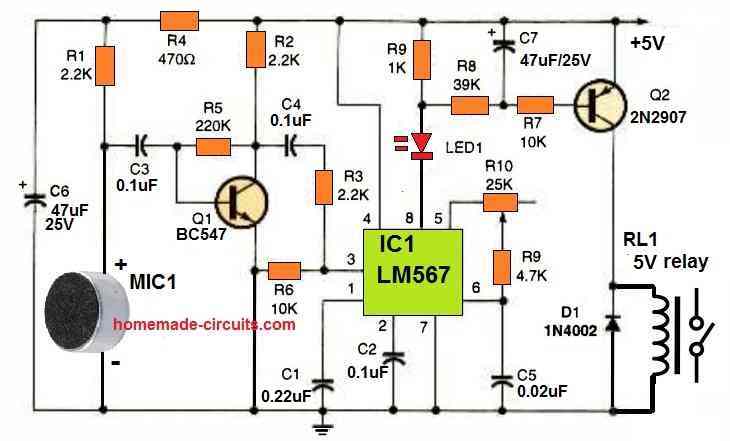
whistle activated switch circuit

Upon identification of the whistle sound, IC1 changes its output at pin 8 to low (0V). This switches ON the LED1 and lowers the resistor R8 to almost ground potential.

A simple time-delay built around the timing components C7 and R8 prevents the relay from chattering because of voices and background noises that occur within the IC1 LM567's wavelength.

By adjusting the value of capacitor C7, the delay may be changed. A higher value means more delay, while a lower value means less delay.

For RL1, just about any 5 V SPDT relay will work as long as the coil resistance is between 200 and 500 ohms.

Consider the required load switching operation while choosing the relay's contact ratings. The part values provided should allow the circuit to detect whistle frequencies between 1 kHz and 15 kHz.

To adjust the frequency detecting tuning range of IC1, simply modify the value of capacitor C5.

For a lower frequency range, make C5 value bigger; and for a higher frequency range, make C5 value smaller.

You can use a toy whistle if you are unable to whistle or produce the same pitch repeatedly.

Parts List

  • SEMICONDUCTORS
  • D1- 1N4002, 1 amp, 100 PIV, general purpose rectifier diode
  • IC1 - LM567 PLL tone decoder IC
  • LED1 - LED, any color
  • Q1 - BC547 NPN or any other NPN equivalent
  • Q2 - 2N2907 PNP or any other PNP equivalent
  • RESISTORS
  • (All fixed resistors are 1/4 watt, 5% rated)
  • R1, R2, R3 - 2.2 K
  • R4 - 470 ohm
  • R5 - 220 K
  • R6, R7 - 10 K
  • R8 - 39 K
  • R9 - 4.7 K
  • R10 - 25 K potentiometer
  • CAPACITORS
  • C1 - 0.22 uF ceramic-disc capacitor
  • C2, C3, C4 - 0.1 uF, ceramic disc capacitor
  • C5 - 0.02 µF, mylar, or similar capacitor
  • C6, C7 - 47 uF, 25V , electrolytic capacitor
  • ADDITIONAL PARTS AND MATERIALS
  • MIC1- Electret-type microphone
  • RL1 - 5 V relay, Whistle, cabinet, power source, etc.

Advantages

The main advantages of this whistle controlled switch circuit are as I have explained below:

  • The circuit is cheap to build and use
  • It can be used like a remote control for activating a load with whistle sound
  • No complex transmitter handset is required.
  • Requires ordinary electronic components to assemble the unit.
  • The frequency of the circuit can be customized for activating with any other desired frequency.

Disadvantages

The couple disadvantages of this whistle activated switch circuit can be summarized as given below:

  • Whistling may create disturbance and annoyance to the other people around.
  • Anybody can activate the load using a whistling sound.

You'll also like:

  • 1.  Remote Control using Mains Power Line Communication
  • 2.  Cheap Cellphone Controlled Water Pump for Farmers
  • 3.  Make this IR Remote Control Range Extender Circuit
  • 4.  Remote Control Circuit Using FM Radio
  • 5.  Remote Controlled Fish Feeder Circuit – Solenoid Controlled
  • 6.  Remote Controlled Night Lamp Circuit

About Swagatam

I am an electronics engineer with over 15 years of hands-on experience. I am passionate about inventing, designing electronic circuits and PCBs, and helping hobbyists bring their projects to life. That is why I founded homemade-circuits.com, a website where I share innovative circuit ideas and tutorials. Have a circuit related question? Leave a comment.... I guarantee a reply!

Previous Post: « AC Ammeter Circuit for Measuring Current across 220 V Appliances
Next Post: Blinking LED Circuit using LDR and Resistors »

Reader Interactions

Need Help? Please Leave a Comment! We value your input—Kindly keep it relevant to the above topic! Cancel reply

Your email address will not be published. Required fields are marked *

Primary Sidebar

Subscribe to New Circuit Ideas

Categories

  • Arduino Projects (87)
  • Audio and Amplifier Projects (132)
  • Automation Projects (17)
  • Automobile Electronics (101)
  • Battery Charger Circuits (83)
  • Datasheets and Components (104)
  • Electronics Theory (143)
  • Free Energy (37)
  • Games and Sports Projects (11)
  • Grid and 3-Phase (19)
  • Health related Projects (25)
  • Home Electrical Circuits (12)
  • Indicator Circuits (14)
  • Inverter Circuits (87)
  • Lamps and Lights (142)
  • Meters and Testers (69)
  • Mini Projects (46)
  • Motor Controller (64)
  • Oscillator Circuits (27)
  • Pets and Pests (15)
  • Power Supply Circuits (108)
  • Remote Control Circuits (50)
  • Security and Alarm (64)
  • Sensors and Detectors (101)
  • Solar Controller Circuits (59)
  • Temperature Controllers (42)
  • Timer and Delay Relay (49)
  • Transmitter Circuits (29)
  • Voltage Control and Protection (37)
  • Water Controller (36)

Calculators

  • Battery Back up Time Calculator
  • Capacitance Reactance Calculator
  • IC 555 Astable Calculator
  • IC 555 Monostable Calculator
  • Inductance Calculator
  • LC Resonance Calculator
  • LM317, LM338, LM396 Calculator
  • Ohm’s Law Calculator
  • Phase Angle Phase Shift Calculator
  • Power Factor (PF) Calculator
  • Reactance Calculator
  • Transistor Astable Calculator
  • Transistor base Resistor Calculator
  • Voltage Divider Calculator
  • Wire Current Calculator
  • Zener Diode Calculator
  • Filter Capacitor Calculator
  • Buck Converter Calculator
  • Boost Converter Calculator
  • Solar Panel, Inverter, Battery Calculator
  • Wire Current Calculator
  • SMPS Transformer Calculator
  • IC SG3525, SG3524 Calculator
  • Inverter LC Filter Calculator

People Also Search

555 Circuits | 741 Circuits | LM324 Circuits | LM338 Circuits | 4017 Circuits | Ultrasonic Projects | SMPS Projects | Christmas Projects | MOSFETs | Radio Circuits | Laser Circuits | PIR Projects |

Recent Comments

  • Swagatam on Real MPPT Solar Charger Circuit Using Arduino, LCD, and Manual/Auto Switch
  • Obaidullah Khan on Real MPPT Solar Charger Circuit Using Arduino, LCD, and Manual/Auto Switch
  • Swagatam on 2 Compact 12V 2 Amp SMPS Circuit for LED Driver
  • Alan Bishop on AC Motor Speed Controller Circuits using Back EMF
  • Swagatam on Real MPPT Solar Charger Circuit Using Arduino, LCD, and Manual/Auto Switch

Company

  • Privacy Policy
  • Cookie Policy
  • About Me
  • Contact
  • Disclaimer
  • Copyright
  • Videos
  • Sitemap

Social Profiles

  • Twitter
  • YouTube
  • Instagram
  • Pinterest
  • My Facebook-Page
  • Quora
  • Stack Exchange
  • Linkedin
  • © 2025 · Swagatam Innovations