In this post I have explained how to use an exercise bike or a treadmill for charging a battery through a simple shunt regulator circuit with full charge cut-off feature. The idea was proposed by Mr. Peter Jaffe.
Exercise Bike for Charging Battery
I have been following your circuit tips for a little while. Very helpful and informative! I was wondering if you can help me out.
This is the deal. I have a beautiful recumbent exercise bike I inherited from my dad. Its a TRUE PS/100. It has a three phase induction AC motor. 250watts at 1amp.
I also have a small solar system. 5 X 38wah Lithium Ion Batteries 12V in parallel. They are hooked up to two 245 watt 10amp (each) Poly Panels. The solar system works great...getting 18-19amps at peak sun...more than enough to charge the system.
Now..on cloudy or rainy days..and obviously at night I am not getting any power into my lithium battery bank.
So.... here's the question.... I have wanted to utilize my exercise bike to install a bridge rectifier..(which I did)...three phase AC to single phase DC...the problem is...its still too much voltage to charge my 12 volt battery bank with.... how can I step down the voltage to 24volts (from @150-200 Rectified DC) to lessen the Back EMF coming into the bike which makes it difficult to peddle...and lower the voltage so I don't blow the batteries??... What type of circuit do you suggest?
Resistors? 400volt caps? a transistor perhaps?? I'm not formally trained in circuit..design. Please help! Thanks!
Regards,
Peter Jaffe
The Design
Initially it appeared to me that the request was regarding operating the bike from alternative source but after reading it the second time I realized that actually it's regarding using the exercise bike for charging batteries by generating electricity from the bike motor.
The easiest way to use a treadmill as a battery charger is by reducing its voltage through a shunt regulator circuit.
I have already discussed a few shunt regulator circuits in this website, which can be viewed through the following relevant links:
Motorcycle Full Wave Shunt Regulator Circuit
Motorcycle Shunt Regulator Circuit using SCR
Although the above circuits would do the job quite well and allow the exercise bike output to charge the Li-ion batteries safely, the user would experience some resistance to peddle at higher speeds, which could make things a little stressful, however this might happen only if the user tries to peddle too fast.
Circuit Diagram
Circuit Operation
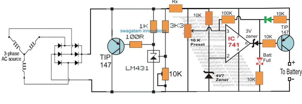
Referring to the proposed treadmill battery charger circuit above, we can see a 6 diode rectifier bridge attached with the motor output of the treadmill for acquiring the required DC charging voltage from it.
The output from the bridge rectifier is directly applied across the shunt regulator for the necessary regulation at the set voltage.
The shunt voltage level is fixed by adjusting the 10K preset associated with the TL431 shunt regulator devicewhich is around 14.4V for the mentioned 12V Li-ion batteries.
Now as soon as the treadmill is operated, the voltage generated by the treadmill or the exercise machine is instantly detected and the excess voltage is shunted by the left side TIP147 transistor in order to maintain a constant voltage at the stipulated value.
This transistor should be mounted over a substantially large heatsink in order to ensure an optimal working performance from it.
This regulated or stabilized shunt voltage is applied to an opamp based over-charge detector circuit which monitors this voltage and switches off the supply to the connected battery as soon as the full-charge level of the battery is reached (equal to the set max shunt regulation level.)
The 100k hysteresis resistor connected across the pin6 and pin3 of the opamp 741 makes sure that as soon as the full-charge level is reached the situation is latched at that level so that no further charging of the battery is allowed until the battery voltage falls to some lower threshold, may be at 13.5V etc which can be set by appropriately calculating or experimenting the indicated hysteresis resistor value.
The resistor Rx is introduced for limiting current to the battery, it may be simply calculated by using the following formula:
R = V/I,
where V is the full charge voltage, and I is specified maximum safe current limit for the battery.


Comments
I’m interested in having an exercise bike that charges batteries. I found a battery charger that you pedal, but it is not meant for exercise. It is too easy to pedal, but it is a good format. This post intrigues me. Am I correct in assuming the the resistance is a separate system from the power generation? Meaning that the majority of the work being done is not being channeled into the AC motor? I would like to have something that would convert the majority of work into electricity. Any ideas?
The resistance refers to the load on the motor. If the load increases the resistance also increases and you find it harder to pedal. As your battery charges, the load current decreases proportionately, and you find it easier and easier to pedal.