In this project we are going to interface a digital potentiometer with arduino. In this demonstration potentiometer MCP41010 is used but you can use any digital potentiometer of MC41** series.
By Ankit Negi
INTRODUCTION TO MC41010
Digital potentiometers are just like any analog potentiometer with three terminals with only one difference. Whereas in analog one you have to manually change the wiper position, In case of digital potentiometer wiper position is set according to the signal given to potentiometer using any microcontroller or microprocessor.
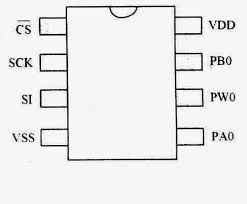
FIG. MC41010 IC pinout
MC41010 is an 8 pin dual in line package IC. Just like any analog potentiometer this IC comes in 5k, 10k, 50k, and 100k. In this circuit 10k potentiometer is used
MC4131 have following 8 terminals:
Pin no. Pin Name Little description
1 CS This pin is used to select the slave or peripheral connected to arduino. If this is
Low then MC41010 is selected and if this is high then MC41010 is deselected.
2 SCLK Shared/Serial Clock, arduino gives clock for initialization of data transfer from
Arduino to IC and vice versa.
3 SDI/SDO Serial data is transferred between arduino and IC through this pin
4 VSS Ground terminal of arduino is connected to this pin of IC.
5 PA0 This is one terminal of the potentiometer.
6 PW0 This terminal is wiper terminal of the potentiometer( to change resistance)
7 PB0 This is another terminal of the potentiometer.
8 VCC Power to IC is given through this pin.
This IC contains only one potentiometer. Some IC have at most two potentiometer inbuilt. This
The value of the resistance between wiper and any other terminal is changed in 256 steps, from 0 to 255. Since we are using a 10k resistor value of resistor is changed in steps of:
10k/256= 39 ohms per step between 0 and 255
COMPONENTS
We need following components for this project.
1. ARDUINO
2. MC41010 IC
3. 220 OHM RESISTOR
4. LED
5. CONNECTING WIRES
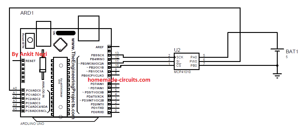
Make connections as shown in fig.
1. Connect cs pin to digital pin 10.
2. Connect SCK pin to digital pin 13.
3. Connect SDI/SDO pin to digital pin 11.
4. VSS to ground pin of arduino
5. PA0 to 5v pin of arduino
6. PB0 to ground of arduino
7. PWO to analog pin A0 of arduino.
8. VCC to 5 v of arduino.
PROGRAM CODE 1
This code prints the voltage change across wiper terminal and ground on Serial Monitor of Arduino IDE.
#include <SPI.h>

int CS = 10;          // Chip Select pin for digital potentiometer
int x;                // Variable to store analog read value
float Voltage;        // Variable to store calculated voltage

void setup() {
  pinMode(CS, OUTPUT); // Set CS pin as output
  pinMode(A0, INPUT);  // Set A0 as input
  SPI.begin();         // Initialize SPI communication
  Serial.begin(9600);  // Initialize serial communication
}

void loop() {
  // Ramp up from 0 to 255
  for (int i = 0; i <= 255; i++) {
    digitalPotWrite(i);
    delay(10);
    readAndPrintVoltage(i);
  }

  delay(500);

  // Ramp down from 255 to 0
  for (int i = 255; i >= 0; i--) {
    digitalPotWrite(i);
    delay(10);
    readAndPrintVoltage(i);
  }
}

// Function to write value to the digital potentiometer
int digitalPotWrite(int value) {
  digitalWrite(CS, LOW);
  SPI.transfer(B00010001); // Command byte
  SPI.transfer(value);      // Data byte
  digitalWrite(CS, HIGH);
  return value;
}

// Function to read analog voltage and print to Serial
void readAndPrintVoltage(int level) {
  x = analogRead(A0);
  Voltage = (x * 5.0) / 1024.0;
  Serial.print("Level i = ");
  Serial.print(level);
  Serial.print("\t Voltage = ");
  Serial.println(Voltage, 3);
}
EXPLAINING CODE 1:
To use digital potentiometer with arduino you need to include SPI library first which is provided in arduino IDE itself. Just call the library with this command:
#include <SPI.h>
In void setup, pins are assigned as output or input. And commands to begin SPI and serial communication between arduino and ic is also given which are:
SPI.begin(); and
 Serial.begin(9600);
In void loop, for loop is used to change the resistance of digital pot in total 256 steps. First from 0 to 255 and then again back to 0 with 10 milliseconds delay between each step:
for (int i = 0; i <= 255; i++) and
 for (int i = 255; i >= 0; i--)
digitalPotWrite(i) function writes theese value to change resistance at particular address of ic.
Resistance between wiper and end terminal can be calculated using these formulae:
R1= 10k*(256-level)/256 + Rw
And
R2= 10k*level/256 + Rw
Here R1= resistance between wiper and one terminal
R2= resistance between wiper and other terminal
Level = step at a particular instant ( variable “I” used in for loop)
Rw= resistance of wiper terminal ( can be found in datasheet of the ic )
Using digitalPotWrite() function the digital potentiometer chip is selected by assigning LOW voltage to CS pin. Now as the ic is selected, an address must be called on which data will be written. In the last portion of code :
SPI.transfer(B00010001);
Address is called which is B00010001 to select the wiper terminal of the ic on which data will be written. And hence for loop’s value i.e, i is written to change the resistance.
CIRCUIT WORKING:
As long as value of i keeps changing input to A0 pin of arduino also keeps changing between 0 and 1023. This happens because wiper terminal is directly connected to A0 pin, and other terminal of potentiometer are connected to 5volt and ground respectively. Now when resistance changes so do voltage across it which is directly taken by arduino as input and thus we get a voltage value on serial monitor for a particular value of resistance.
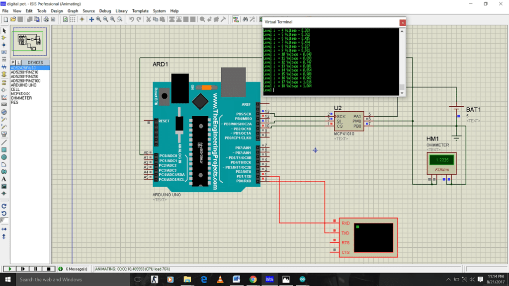
SIMULATION 1:

These are some simulation pictures for this circuit at various values of i:
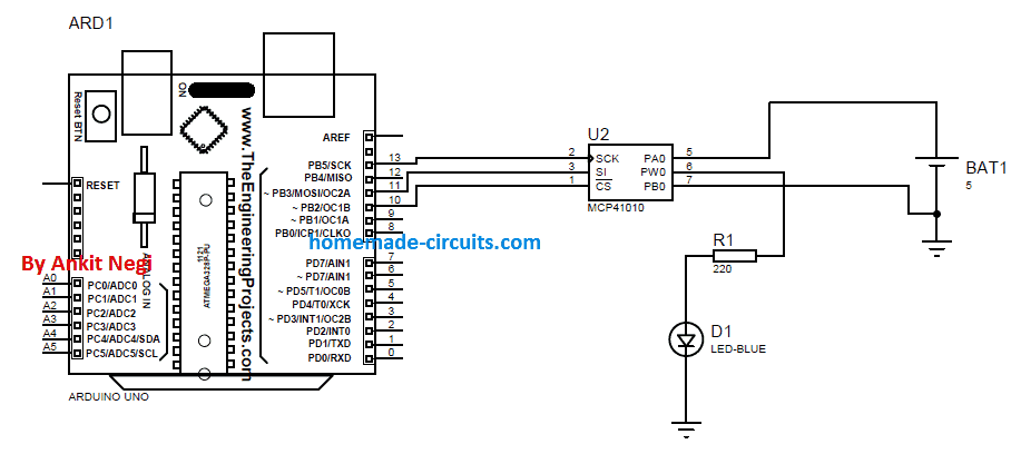
Now just connect an led in series with 220ohm resistor to wiper terminal of IC as shown in figure.
CODE 2:
#include <SPI.h>

// Pin definitions
const int CS = 10;   // Chip Select for digital potentiometer

// Variables
int x;
float Voltage;
int i;

void setup() {
  pinMode(CS, OUTPUT);   // Set CS as output
  pinMode(A0, INPUT);    // Analog input (not used here yet)
  SPI.begin();            // Initialize SPI communication
}

void loop() {
  // Increase potentiometer value from 0 to 255
  for (int i = 0; i <= 255; i++) {
    digitalPotWrite(i);  // Set digital potentiometer
    delay(10);           // 10 ms delay between steps
  }
  delay(500);            // Wait half a second at max value

  // Decrease potentiometer value from 255 to 0
  for (int i = 255; i >= 0; i--) {
    digitalPotWrite(i);
    delay(10);
  }
}

// Function to write value to digital potentiometer via SPI
void digitalPotWrite(int value) {
  digitalWrite(CS, LOW);           // Select the device
  SPI.transfer(B00010001);         // Command byte (depends on IC)
  SPI.transfer(value);             // Send value (0-255)
  digitalWrite(CS, HIGH);          // Deselect the device
}
EXPLAINING CODE 2:
This code is similar to code 1 except that there are no serial commands in this code. So no values will be printed on serial monitor.
WORKING EXPLANATION
Since led is connected between wiper terminal and ground as resistance changes so do voltage across led. And hence as resistance across which led is connected rises from 0ohm to maximum so do brightness of led. Which again slowly fade away due to decrease in resistance from maximum to 0v.
Simulation2

Simulation3


Comments
sir is there any ic or cheap circuit which has clock timing features.that thing should have following features.. uninterrupted timing system like watch am pm everything, programmable one or more output which give signal at perfect predefined tym by me .
i dont want ic like 555timer i want timing circuit like watch clock.
i hope u got it what i want.
Gurmel, you can use IC 4060 and configure it with a crystal, that will enable the IC to oscillate with precise clocks.