A cellphone controlled dog feeder is feeding system for pets and animals which allows a remote controlled refilling of food in the container of the feeder by the owner, without physically attending the place.
A GSM module and Arduino based dog feeder circuit is discussed in this post. The system can be used for operating a dog feeder mechanism through the owner's cellphone whenever it may be required.

The idea was requested by Mr. Allan Guillermo through one of his comments
Introduction
Although all domestic animal species are lovable, dogs tend to get much higher preference as pets, perhaps due to their high level of intelligence and loyalty towards the owner.
However with today's growing hectic schedules many pet owners face huge problems managing their pets during their work hours.
Feeding a pet on time becomes a major issue for all the busy pet owners. Pet owners often look for a possible solution that may ensure their pets are never forced to stay hungry or go through untimely food patterns.
To solve this problem, the idea discussed here may provide the much needed solution to everybody facing the above discussed concern.
Objective
The objective of the circuit is to enable the user to know when the food in the container is empty, and to refill it with a quick call from his/her cellphone.
With this facility the pet owners will never have to worry regarding timely supply of food to their pets even while they are away from home.
Using a GSM based Arduino System
In this concept, a GSM module is used as the receiver which accepts a command from the owners cellphone for implementing a practical operation, and also sends an SMS text whenever the relevant issue is detected.
We will need the following units for building the system:
1) GSM Module
2) Arduino board
3) A few electronic spare parts
4) Motor Mechanism
Circuit Diagram

Making the GSM Receiver Stage
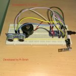
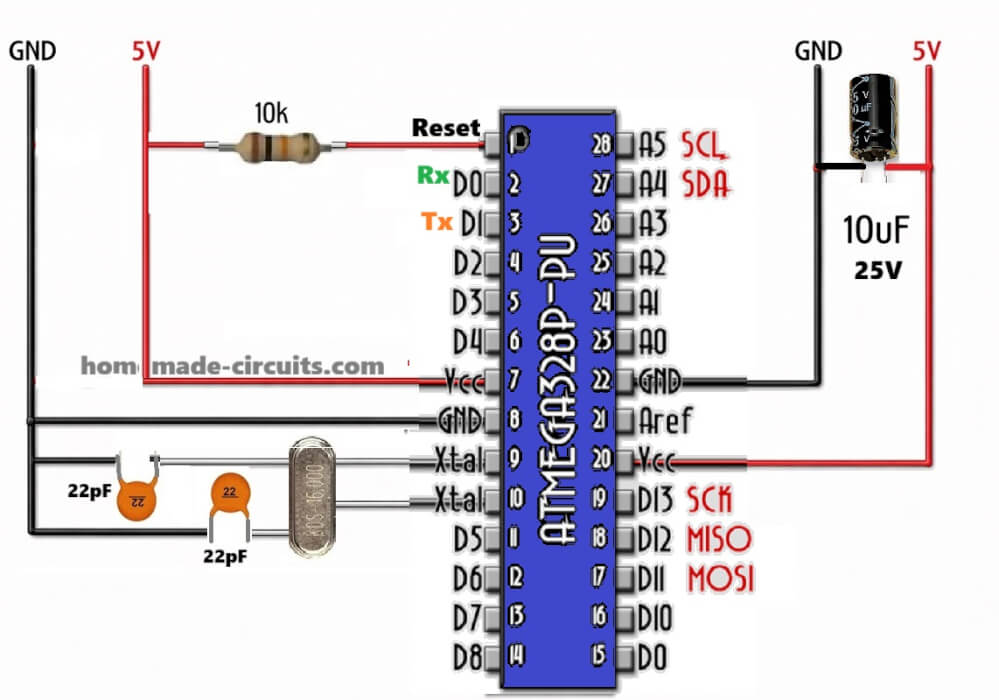
The diagram above shows the GSM receiver circuit, using a GSM module and an Arduino UNO board.
The function of this design is to receive the command from the owners cellphone and operate the attached relay.
The relay finally switches ON a motor mechanism or a solenoid for executing the intended dog feeder operation.
The set up looks quite understandable, except the inclusion of the reed relay.
The reed relay is introduced for sensing the presence, or absence of dog food in the given container.
How the Reed Relay is Supposed to be Arranged
The reed relay is used for triggering a +5V (high) or a 0V (LOW) signal to pin#7 of Arduino. This signal then prompts the Arduino to send a text message to the owner's cellphone, through the GSM module.
The owner thus becomes aware of the situation of the food in the container, whether it is filled or is empty. As per this situation, the owner quickly sends back a command to the GSM module through his cellphone for actuating the feeder system, so that it yet again fills the container with food.
For enabling the reed relay to operate, the dog food container will need to be modified such that it tilts down or presses down by around a cm when it is loaded with food. And moves up or tilts up in the absence of load or the food.
A small magnet introduced at the tilting side comes near the reed relay when the container is loaded and moves away when the container is empty.
Depending upon the above situations the reed relay sends a positive or a negative signal to pin#7 of Arduino, prompting it to send a text message to the owner.
How the Motor Mechanism may Work
The motor mechanism could be arranged such that when activated it opens the feeder door by pushing a spring loaded mechanism.
During this time the feeder bowl starts filling and its weight eventually causes the reed relay to send a positive signal to the Arduino.
When this happens the owner is quickly prompted with a text message acknowledging the filling of the food container.
At this point the user has to send another call to the Arduino GSM, so that the solenoid or the motor mechanism reverts to its original condition closing the door of the feeder.
The above explained motor mechanism and reed relay arrangement could be customized in many different ways as per user convenience and suitability.
Program Code:
The program code is the same as described in the following article.
Please use the code explained at the bottom section of the following article, not the first one.
https://www.homemade-circuits.com/2016/11/gsm-pump-motor-controller-using-arduino.html


Need Help? Please Leave a Comment! We value your input—Kindly keep it relevant to the above topic!