You may find electronic circuits that frequently utilize triacs to manage mains powered loads. However, these setups commonly feature an inconspicuous capacitor and resistor combination across the triac – a snubber network.
The functions of these components are more intricate than they seem. Exploring snubbers and grasping basic triac theory is valuable.
Triac Operation
A triac can be activated through various methods. Applying a suitable gate current is a straightforward approach.
It can also be triggered by surpassing the triac's blocking voltage.
Unlike some semiconductors, a triac is resilient against excessive voltage, as it enters regular conduction rather than destructive breakdown.
A third method involves inducing a rapid voltage change across the triac.
If the voltage alteration surpasses a critical level, the triac activates, even if the voltage is below its rated blocking voltage (VDRM).
The latter two methods are often troublesome, and snubbers are employed to avert unintentional triac activation.
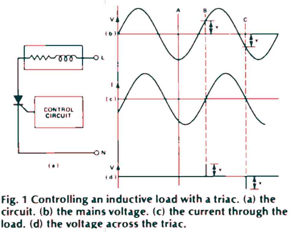
Fig. 1(a): The Inductive Load Scenario: In this illustration, the triac manages an inductive load, represented by an inductor and resistor. The control circuit supplies gate current for triac activation, and turning off relies on reducing triac current to zero (or below its holding current).
Fig. 1(b): Voltage across Triac and Load: Depicts the mains voltage acting as the load, resulting in voltage across the triac.
Fig. 1(c): Triac Current Lag: Illustrates that the current through the triac lags behind the mains voltage due to the inductive load's characteristics.
The Snubber's Role
Consider the scenario at point A where the control circuit withdraws gate current from the triac, aiming to turn it off when current hits zero.
At point B, the triac indeed switches off. However, due to the present voltage across the circuit, the voltage across the triac surges rapidly (as shown in Fig. 1(c)), leading it to re-activate immediately.
At point C, the same pattern occurs in reverse polarity, perpetuating the cycle. Consequently, the triac remains in the active state and won't turn off.
Adding a Capacitor
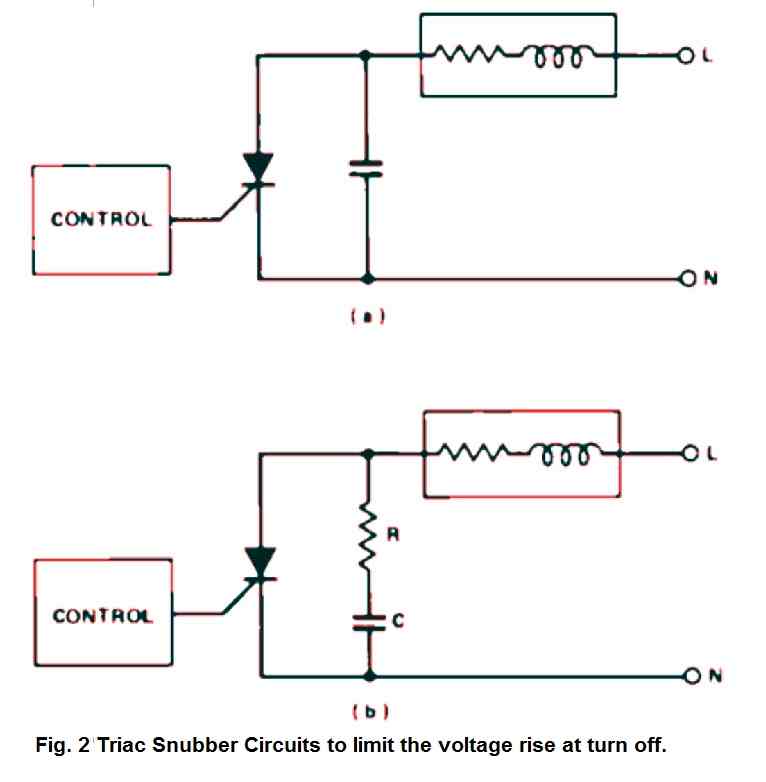
When initially addressing the issue of sudden voltage spikes, a common inclination is to place a capacitor across the triac, as demonstrated in Fig. 2(a).
However, this solution is not effective. If the triac switches on when the capacitor is charged to the peak mains voltage, it accumulates substantial energy that the triac must then dissipate.
Importantly, during turn-on, the surge current capacity of a triac is significantly lower than specified in data sheets, leading to unexpected circuit failures.
Standard Snubber Design
By integrating a resistor in series with the capacitor, not only does the surge current get limited (and this resistor serves another function to be discussed later), but it establishes the conventional snubber layout showcased in Fig. 2(b).
Complexities of Snubber Behavior
Despite adopting the standard snubber arrangement, its performance isn't always guaranteed.
To confidently identify suitable component values for various scenarios, a closer examination of the snubber's impact is necessary.
Transient Conditions During Turn-Off: Oscillation Concerns
During triac turn-off, the snubber capacitor is discharged, the inductor current reaches zero, and the snubber and load exhibit a voltage 'v'.
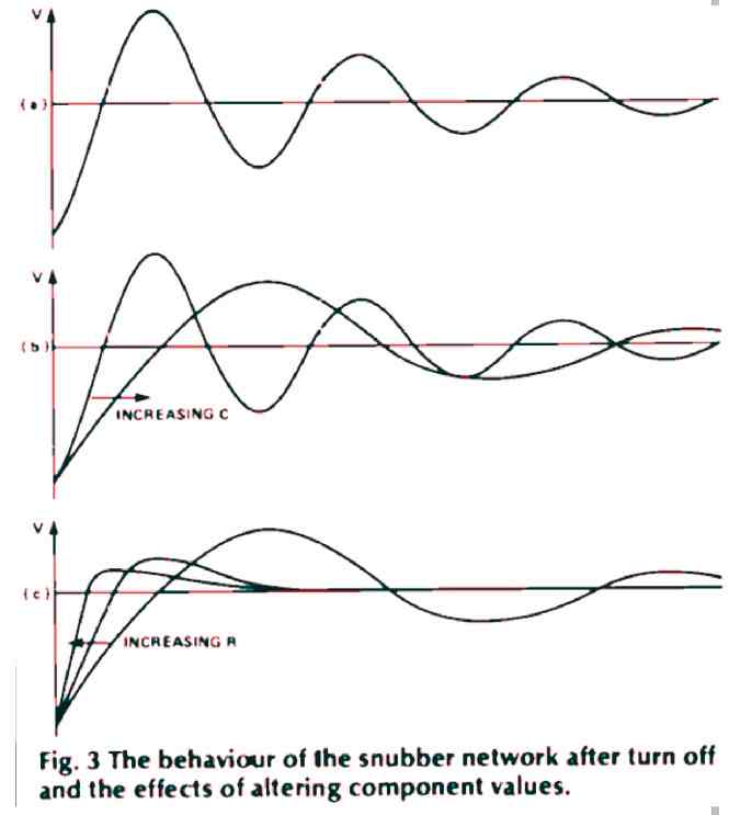
This situation transforms the combination of load and snubber into an RLC circuit experiencing an abrupt voltage transition. Depending on component values, the circuit tends to oscillate (as depicted in Fig. 3(a)).
Impact of Oscillation on Triac Behavior
In cases where load inductance is high and series resistance is low, the voltage 'v' across the triac during turn-off approaches the peak mains voltage.
The first oscillation cycle can peak at nearly 2v, almost twice the mains peak voltage. This poses a challenge for triacs with a VDRM of 400V, as they might re-activate before voltage reaches its peak.
Tuning the Snubber
Balancing component values is crucial to mitigate the problems mentioned above. Increasing capacitor 'C' reduces the initial rate of voltage rise across the triac and dampens oscillations, as shown in Fig. 3(b).
Elevating the snubber resistor value also dampens oscillations, but it accelerates the rate of voltage change across the triac.
Achieving a harmonious balance requires adjusting both values to keep the initial overshoot below the triac's VDRM while maintaining a controlled rate of voltage change.
Challenges with High-Inductance Loads
Standard snubber components might not suit loads with high inductance and low resistance, such as solenoids or heavy-duty contactors.
Such cases can approach resonance at 50Hz, causing complications.
Capacitance values around 1µF could be problematic, as even smaller values might energize the load or damage the snubber resistor due to excessive current flow.
Customizing for Complex Loads
While most loads conform to standard component values, those with low resistance and substantial inductance warrant special attention.
Loads with low resistance and inductance below 1H might require a capacitor exceeding 100nF to regulate voltage rise.
For high-inductance loads, adjusting capacitor 'C' becomes necessary, and the appropriate snubber resistor value can be calculated using a formula.
A Complex yet Customizable Solution
Despite the challenges outlined, many loads can be managed effectively with standard snubber networks.
Load complexities arise primarily from low resistance and inductance characteristics.
By understanding the effects of component adjustments and employing rule-of-thumb calculations, suitable snubber values can be derived for varying load scenarios.
Determining Capacitor and Resistor Values
Setting the Upper Limit for Capacitor Value Avoiding Excessive Current: Ensuring that excessive current doesn't flow through the snubber and load at mains frequency dictates an upper limit for capacitor 'C'.
One practical guideline is to calculate the value of 'C' needed for resonance at 50Hz and then divide it by 20 to establish the maximum usable value.
Calculating Capacitor Values for Different Loads: For a load with 10H inductance, 'C' should be 50n or less. Similarly, for 1H inductance, the value should stay below 500n, and so forth.
Determining the Lowest Usable 'C' Value: Considering Voltage Rate of Change: The smallest usable 'C' value hinges on the triac's voltage rate of change capacity, often termed 'critical d'.
This value, usually found in the data sheet, is expressed as volts per microsecond. A common small triac might feature a typical value of 100V/µs.
Calculating the Minimum 'C' Value: To determine the smallest usable 'C' value, employ the formula:
C (in pF) = v2 / [(dv/dt)2 x L]
Where 'dv/dt' is the critical value from the datasheet, 'L' is the load's inductance, and 'v' is the voltage across the circuit when the triac turns off.
If unable to measure 'L', it's prudent to estimate conservatively.
For 'v', the peak mains voltage can be employed – the worst-case scenario for a pure inductance load.
Choosing an Appropriate 'C' Value: With the maximum and minimum 'C' values established, opt for a value in between.
Calculating 'R' for Critical Damping: Utilize the formula:
R = 2√(L/C - RL)
Where 'RL' represents the load's resistance.
Resistor Selection:
- If the calculated 'R' is below 30 ohms, select a 33R resistor to prevent turn-on current issues.
- If 'R' is higher, increase the result by 50% and use this value for 'R' to achieve over-damping, ensuring circuit stability.
Comprehensive Solution for Diverse Scenarios
Employing these calculations offers a robust approach for addressing various triac snubber network scenarios. Implementing the recommended capacitor and resistor values ensures that triacs reliably turn off without encountering failures.

Comments
Good Evening,
first of all congratulations for your nice article and your excellent site.
I would like to ask how can I calculate the values when the load consists of a motor with two coils and a capacitor.
thanks in advance
Thank you Haris,
The snubber formula for the triac will be the same for all types of motors, according to me.