In this article I have explained the pinout functions of the IC SG3525 which is a regulating pulse width modulator IC. So I have explained in details:
Main Technical Features
The main features of the IC SG3525 may be understood with the following points:
- Operating voltage = 8 to 35V
- Error amp reference voltage internally regulated to 5.1V
- Oscillator frequency is variable through an external resistor within the range of 100Hz to 500 kHz.
- Facilitates a separate oscillator sync pinout.
- Dead time control is also variable as per intended specs.
- Has an internal soft start feature
- Shut down facility features a pulse by pulse shutdown enhancement.
- Input under voltage shut down feature also is included.
- PWM pulses are controlled through latching for inhibiting multiple pulse outputs or generation.
- Output supports a dual totem pole driver configuration.
Pinout Diagram of the IC
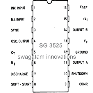
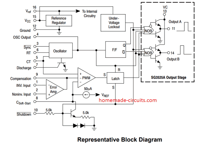
SG3525 PinOut Description
A practical implementation of the following pinout data may be understood through this inverter circuit
The IC SG3525 is a single package multi function PWM generator IC, the main operations of the respective pin outs are explained with the following points:
Pin#1 and #2 (EA inputs): These are inputs of the built-in error amplifier of the IC. Pin#1 is the inverting input while pin#2 is the complementary non-inverting input.
It's a simple op amp arrangement inside the IC which controls the PWM of the IC outputs at Pin#11 and Pin#14. Thus these EA pins 1 and 2 can be effectively configured for implementing an automatic the output voltage correction of a converter.
It is usually done by applying a feedback voltage from the output through a voltage divider network to the non-inverting input of the op amp (pin#1).
The feedback voltage should be adjusted to be just below the internal reference voltage value (5.1 V) when the output is normal.
Now, if the output voltage tends to increase above this set limit, the feedback voltage would also increase proportionately and at some point exceed the reference limit. This will prompt the IC to take necessary corrective measures by adjusting the output PWM, so that the voltage is restricted to the normal level.
Pin#3 (Sync): This pinout can be used for synchronizing the IC with an external oscillator frequency. This is generally done when more than a single IC is used and requires to be controlled with a common oscillator frequency.
Pin#4 (Osc. Out): It's the oscillator output of the IC, the frequency of the IC may be confirmed at this pin out.
Pin#5 and #6 (Ct, Rt): These are termed CT, RT respectively. Basically these pinouts are connected with an external resistor and a capacitor for setting up the frequency of the inbuilt oscillator stage or circuit. Ct must be attached with a calculated capacitor while the Rt pin with a resistor for optimizing the frequency of the IC.
The formula for calculating the frequency of IC SG3525 with respect to RT and CT is given below:
f = 1 / Ct(0.7RT + 3RD)
- Where, f = Frequency (in Hertz)
- CT = Timing Capacitor at pin#5 (in Farads)
- RT = Timing Resistor at pin#6 (in Ohms)
- RD = Deadtime resistor connected between pin#5 and pin#7 (in Ohms)
Pin#7 (discharge): This pinout can be used for determining the deadtime of the IC, meaning the time gap between the switching of the two outputs of the IC (A and B). A resistor connected across this pin#7 and pin#5 fixes the dead time of the IC.
Pin#8 (Soft Start): This pinout as the name suggests is used for initiating the operations of the IC softly instead of a sudden or an abrupt start. The capacitor connected across this pin and ground decides the level of soft initialization of the output of the IC.
Pin#9 (Compensation): This pinout is for compensating the error amplifier op amp. Mostly this pinout is connected to ground via a RC network. However, if required this pinout can be configured with an external transistor which can ground this pin during a critical situation, enabling a shutdown of the IC output.
Why Compensation Network is Required at pin#9
See, if you connect feedback directly without compensation then things do not stay calm, they start misbehaving.
The system can oscillate, like it keeps shaking instead of settling. Output voltage can go up and down.
If load changes then it may become unstable, especially under sudden load change and then you may see strange behavior.
We therefore do not leave it just open..
So we connect a resistor. We also connect a capacitor. Sometimes an RC network between Pin#9 and ground, but sometimes also to feedback pin, depends on how it is arranged.
This then forms what we call a compensation network for the SG3525 IC.
Pin#10 (Shutdown): As the name suggest this pinout may be used for shutting down the outputs of the IC in an event of a circuit malfunction or some drastic conditions.
A logic high at this pin out will instantly narrow down the PWM pulses to the maximum possible level making the output device's current go down to minimal levels.
However if the logic high persists for longer period of time, the IC prompts the slow start capacitor to discharge, initiating a slow turn ON and release. This pinout should not be kept unconnected for avoiding stray signal pick ups.
Pin#11 and #14 (output A and output B): These are the two outputs of the IC which operate in a totem pole configuration or simply in a flip flop or push pull manner.
External devices which are intended for controlling the converter transformers are integrated with these pinouts for implementing the final operations.
Pin#12 (ground): It's the ground pin of the IV or the Vss.
Pin#13 (Vcc): The output to A and B are switched via the supply applied to pin#13. This is normally done via a resistor connected to the main DC supply. Thus this resistor decides the magnitude of trigger current to the output devices.
Pin#15 (Vi): It's the Vcc of the IC, that is the supply input pin.
Pin#16: The internal 5.1V reference is terminated through this pinout and can be used for external reference purposes. Example, you can use this 5.1V for setting up a fixed reference for a low battery cut-off op amp circuit, etc. If it's not used then this pin must be grounded with a low value capacitor.


Questions & Answers
Just use a 7812 IC for limiting the voltage to 12V for the ICs, rest everything will remain as is.
I have no idea about it, you may take the help of a professional trafo designer.
sir if i want to use pin10 of the sg3524 as shutdown in my inverter how do i make the circuit to sense my battery low voltage and trigger the shutdown
beelal, pls refer to this example for the connection details:
https://www.homemade-circuits.com/2013/01/modified-sine-wave-inverter-circuit.html
Hi
i need help about the sg3524 i build an inverter with it but my problem is that i only get 1.5vac form pin 11 and pin 14 and i know it should be at least 2.5 volt so my inverter is not working please help
check the peak voltage at those pinouts with a peak voltage detector, it should be equal to the battery voltage, or adjust the PWM pin preset for correcting the output to the desired limit.
In any case the mosfets will conduct, albeit with different RMS levels.
I have the same issue.
check the supply voltage, it may be too high or there could be soem other incorrect connections.
Hello sir .i have built a car smps based on sg3525.on off load my dc rectifier heat up gaudily,i am using 12v 1.5 AH power supply.when i attach a car battery my rectifier blows with in seconds and in result my mosfets also blows.i cannot figurout where is the problam.please help me with that.
Hello Nomi, It indicates that your SMPS is wrongly designed or constructed, a bridge will never heat up without load or under correct loads
Dear Sir
I want know how to calculate RT AND CT
Dear Rashabtha,
f = 1.3/Rt.Ct
Rt in kHz, Ct in uF and f in kHz
how do we calculate dead time? whats the formula for Rd
please check the datasheet of the IC, it might be there
Dear Swagatam Sir,
Can I use this IC to synchronise 2 sine waves with a phase difference?
Thanks in advance.
Dear Faris,
please read the pin#3 explanation given in the above article, here sync feature becomes relevant only when more than one IC is involved and all the ICs need to work with a single oscillator frequency, secondly the IC is not designed to respond to sine waves, it'll ultimately convert all frequencies to square waves…
Sir,
can you please suggest me any method by which I can synchronise two sine waves of high voltage?
Faris, you'll have to explain me the whole application that you are trying to implement, only then i'll be able to suggest you something…
If I'm getting no output from A and B and shutdown pin is low, what is causing outputs to stop? Thanks!
shutdown pin should be at "low" to enable the A/B pins functioning….there could be some other fault in your circuit
Hello sir i have constructed an inverter based on sg3524 with 2 irf3205 mosfet which is supposed to deliver 300watt and at the output i get 300vac and adjust it to 220vac using the preset and my transformer is 9-0-9 300va but when i connect a 20watt cfl bulb it works fine but if i connect a 60watt load the output becomes 0v and transformer stops humming but once i remove the 60watt load inverter comes on immediately and after sometime it starts to on itself and off itself at a period of about 3seconds…pls where could the problem come from as i'm using a 12v 36amp battery could this be as a result of faulty battery? Because when i bought the batt. I checked the voltage with a dmm and it reads 21v and then decreases fast to 13volt also i didn't charge it when i bought it before using is anything wrong with the battery? If yes can i still power the inverter with an 18amp bactery as i will buy new one if the new battery i bought would be faulty..thanks in advance
Hello victory,
a good 12V battery of any kind can NEVER show 21V at any cost…so definitely your battery could be severely faulty…and using a battery for an inverter application without charging is another grave fault that one can make…so both ways it's the battery that looks defective.
you can use any AH rated battery, that will not harm your inverter in any manner…but just make sure it's 12v rated for your 9-0-9v trafo inverter
Also this is what i observed the drain voltage of the fet on no load at pin 11 of ic is 10.5v and at pin14 is 8v but when i connect the load to it drain voltage becomes 0 which makes the transformer to stop humming is that a clear indication that it's the battery cos i don't want to buy another battery and end up having the same result and since the inverter is producing the desired voltage i don't see anything wrong with it.
just connect a voltmeter across the battery terminal while the inverter is loaded, if the voltage drops to zero will indicate a faulty battery…you can also try attaching an ammeter in series with the battery positive and check the current while the inverter is loaded…if the current reading is too high then your inverter is faulty.
I want to work with two IC SG3525, both working at 50 kHz but one commanding the other, so that the waves are synchronized outputs A, also the output waveforms B also synchronized.
Please send me a sample schema, my email is jmimbelac@yahoo.es
Thank you
connect the pin4 of the IC which has Rt, Ct configured at 50kHz, with pin3 of the other IC without Rt, Ct….that's all ….now both will be synchronized at 50kHz
Thank you sir, I checked and is correct.
The inverter is faulty i replaced the mosfet with original one as i was deceived with a fake irf3205 mosfet the new one powered a 200watt load very normal and my tv works without noise as if it's a pure sinewave
The inverter is faulty i replaced the mosfet with original one as i was deceived with a fake irf3205 mosfet the new one powered a 200watt load very normal and my tv works without noised
Pls what will be the dc voltage of a 15vac transformer after rectification and is their anything wrong with connecting the dc voltage directly to my 12v 36amp battery Will reversed current from the battery destroy the bridge diodes,,also pls tell me the time that my 12v 36amp batt. Be fully charged when charging with a current of 2amp 3,adding a diode to the positive line after rectification will it reduce the voltage
after smoothing it could be well over 20V, you can use it if the current rating of the trafo is not over 4 amp
No, diodes of the bridge will never get destroyed by the battery power.
yes, after 10 hour of charging at 3 amp rate your battery should fully charged…..a series diode will reduce only 0.7V so that's fine if your trafo is already 15V rated.
sorry, the charging rate should be at least 4 amps…3 amp could take around 20 hours for full charging
Please explain the frequency calculation
Sir can u please suggest what the problem might be i rectified a 12vac and it producer 13,8v with 9amp current and my battery voltage is now 11,4volt and so i NEEDED to charge it but when i connect my multimeter in series with the battery when connected I discovered that the battery is only drawing 0,4 amp whereas the current of my charger is 9amp pls what could be the problem or is that normal? I really need to charge the battery 12v 36amp (2)i also constructed ur automatic changeover circuit using relay but when i connect the load to the pole and initiate mains power to the nc the bulb lights well and once i apply dc to the relay coil it offs the light but i see some sparks inside the relay which makes the light to flicker what could be the pro,
victory,
what did you use for the filter capacitor? make sure it's rated at at least 20,000uF/25V…because after rectification the output from your power supply is supposed to be above 15V, and not 13.8V
for the relay problem, just connect a 220uF/25V capacitor parallel with the relay coil, and check the response
The 15v is it on no load also i want to charge the battery with 14.4v not 15v as 15v will damage
I think I just forgot to tell you that the input current for your 36AH battery should not be more than 5amps…so I think 9amp is way too high….or probably you could use a LM338 current limiter circuit in the middle for correcting the issue.
after connecting the input voltage must drop to your discharged battery's voltage level….if it's 11.5V then initially the connected supply should drop to 11.5V and then gradually rise as the batt begins charging….
15V input will not damage the battery if you use an overcharge cut off circuit or manually switch OFF as soon as the battery reaches 14.4V…
We don't have any high amp voltage regulator here in nigeria although i'm a Biafran
you can try making the simple high amp regulator as explained in the following article:
https://www.homemade-circuits.com/2015/03/100-amp-variable-voltage-power-supply.html
And almost everything here is kinda fake
Thanks sir for the explanation
I want to control pwm duty factor from 0-100% is this possible? i shorted pin 9 & 1 and pin 2 is shorted with 16 and i am using vdr from pin 16 to vary the voltage of pin 1 to control duty factor….
I don't think the connections are correct, it should be as shown in the following article:
https://www.homemade-circuits.com/2013/01/modified-sine-wave-inverter-circuit.html
ignoring the D5 connection, P2 can be used for controlling the duty cycle.
Pls sir for a 12v transformer to output 15v after rectification that will be at peak voltage but when there is lower voltage it gives 12v dc so it's advisable to use a 14-15v transformer
In that case you can use a 24V or 18V trafo and regulate it to 14.4V through a LM338 circuit…this will take care of any low voltage situation and give a perfectly constant output for your battery
We don't have any voltage regulator apart from lm7812 here in nigeria.pls sir can u pls tell me why my sg3524 inverter keeps burning the mosfet after some minuites of operation despite being placed on heatsink and not overloaded i'm only running a 100watt load on it.the mosfet is irf3205..could it be the ic?
Victory, please try connecting the mosfets through BJT drivers as shown in the following example, and see the response:
https://www.homemade-circuits.com/2015/05/simplest-pwm-modified-sine-wave.html
I've tried the bjt stage yet the same thing happens what could be the problem
disconnect the transformer from the mosfets and connect 12V car headlamps across drain and positive of each mosfet, if it still burns then definitely the fault could be assumed to be with the IC output…
by the way did you connect freewheeling diodes across drain and source of each mosfets???