• Skip to main content
  • Skip to primary sidebar

Homemade Circuit Projects

Need circuit help? Post them in the comments! I've answered over 50,000!

Blog | Categories | About | Contact | Calculators-online
You are here: Home / Home Electrical Circuits / Two Tone Door Bell Circuit

Two Tone Door Bell Circuit

Last Updated on November 15, 2023 by Swagatam Leave a Comment

The electronic 2 tone door bell circuit is designed around the popular IC 555. The IC 555 is extensively applied in numerous varieties of timers and also as a basic oscillator circuit. In this particular project both the timer and the oscillator functions of the IC are utilized.

Table of Contents
  • How the Circuit Works
  • Parts List

As soon as the indicated push-button is pushed with our finger, the IC 555 begins oscillating with a specific frequency (tone), and as soon as the push-button is released, the frequency changes, modifying the sound of the tone, and the IC now continues generating this second tone for a specific amount of time period, as determined by the RC time constant of the IC.

Hence, when the bell button is pressed once, we get a two-tone doorbell sound from the speaker which is directly attached to the IC pin#3, and operated directly by the IC 555 output.

How the Circuit Works

Referring to the diagram below, the working of this two tone doorbell circuit can be understood with the help of the following points:

The capacitor C2 gets charged at the start, and the charge reaches the supply level of +9V through resistors R2, R3 and R4.

two tone door bell circuit

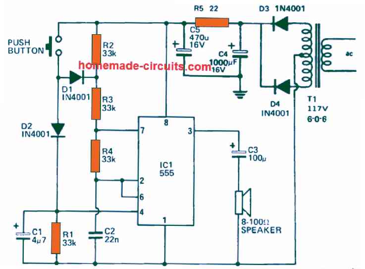
However, because the upper end of the capacitor is linked with both pin#2 and pin#6 of the IC.

Therefore, as soon as the voltage across the capacitor tends to reach 6V level, the two internal comparators of the IC gets above their threshold level, causing the IC 555 at pin#3 to go low, which in turn results in the internal transistor of the IC to switch on.

The action short circuits the pin#7 of the IC to ground.

But, since pin#7 is hooked up with the junction of the resistors R3 and R4 and C2, now begins getting discharged by means of the resistor R4.

During this process as soon as the voltage stored inside C2 tends to drop below 3 V, causes the output of the IC to yet again go high, switching OFF the internal transistor of the IC.

This in turn immediately causes C2 to start charging again by means of the resistor R2, R3 and R4.

This sequence of action goes on repeating continuously, which causes the generation of triangular waveform across C2, creating a train of pulses at the IC output pin#3.

This train of pulses coming out from the pin#3 of the IC can be seen configured with a loudspeaker by means of the capacitor C3.

The C3 capacitor ensures that the dc component present in the pin#3 output voltage does not reach the loudspeaker and thus prevents the loudspeaker from burning.

The capacitor C2 generates the triangular waveform as it charges through 3 V to 6 V and while discharging from 6V to 3V.

If you desire to change the pitch tone of the two tone door bell circuit, to a different tone you just have to tweak the values of the resistors R2, R3, R4 or simply the change the value of C2 appropriately until the desired tone output is achieved.

Parts List

two tone door bell circuit

You'll also like:

  • 1.  Letter Box Open Indicator Circuit
  • 2.  Simple 20 watt Amplifier Circuits
  • 3.  The Perfect FM Radio Circuit using TDA7000 IC
  • 4.  TV Antenna Amplifier Circuit Diagram to Boost TV Signal Reception
  • 5.  5 Simple Preamplifier Circuits Explained
  • 6.  1000 watt to 2000 watt Power Amplifier Circuit Diagram

Filed Under: Home Electrical Circuits, Audio and Amplifier Projects Tagged With: Bell, Door, Tone

About Swagatam

I am an electronics engineer and doing practical hands-on work from more than 15 years now. Building real circuits, testing them and also making PCB layouts by myself. I really love doing all these things like inventing something new, designing electronics and also helping other people like hobby guys who want to make their own cool circuits at home.

And that is the main reason why I started this website homemade-circuits.com, to share different types of circuit ideas..

If you are having any kind of doubt or question related to circuits then just write down your question in the comment box below, I am like always checking, so I guarantee I will reply you for sure!

Previous Post: « Bridged Amplifier Circuit using LM380 Circuit
Next Post: Bench Amplifier Circuit »

Reader Interactions

Need Help? Please Leave a Comment! We value your input—Kindly keep it relevant to the above topic! Cancel reply

Your email address will not be published. Required fields are marked *

Primary Sidebar


Subscribe to New Posts

Categories

  • Arduino Projects (88)
  • Audio and Amplifier Projects (132)
  • Automation Projects (17)
  • Automobile Electronics (101)
  • Battery Charger Circuits (83)
  • Datasheets and Components (104)
  • Electronics Theory (143)
  • Free Energy (37)
  • Games and Sports Projects (11)
  • Grid and 3-Phase (19)
  • Health related Projects (25)
  • Home Electrical Circuits (12)
  • Indicator Circuits (14)
  • Inverter Circuits (88)
  • Lamps and Lights (142)
  • Meters and Testers (69)
  • Mini Projects (46)
  • Motor Controller (64)
  • Oscillator Circuits (27)
  • Pets and Pests (15)
  • Power Supply Circuits (108)
  • Remote Control Circuits (50)
  • Security and Alarm (64)
  • Sensors and Detectors (101)
  • Solar Controller Circuits (59)
  • Temperature Controllers (42)
  • Timer and Delay Relay (49)
  • Transmitter Circuits (29)
  • Voltage Control and Protection (37)
  • Water Controller (36)

Tags

Alarm Amplifier Application Arduino Automatic Battery Charger Circuits Control Controlled Controller Current Datasheet DC Detector Digital Driver Electronic Explained Explored Generator High Indicator Inverter Lamp LED Light Meter Motor Pinout Power Regulator Remote Sensor Simple Single Solar Supply Switch Timer Transistor Voltage Water Watt Working


Other Links

  • Privacy Policy
  • Cookie Policy
  • Disclaimer
  • Copyright
  • Videos
  • Sitemap


People also Search

555 Circuits | 741 Circuits | LM324 Circuits | LM338 Circuits | 4017 Circuits | Ultrasonic Projects | SMPS Projects | Christmas Projects | MOSFETs | Radio Circuits | Laser Circuits | PIR Projects |

Social Profiles

  • Twitter
  • YouTube
  • Instagram
  • Pinterest
  • My Facebook-Page
  • Quora
  • Stack Exchange
  • Linkedin


  • Recent Comments

    • Swagatam on 7 Modified Sine Wave Inverter Circuits Explored – 100W to 3kVA
    • Victor on 7 Modified Sine Wave Inverter Circuits Explored – 100W to 3kVA
    • Victor on 7 Modified Sine Wave Inverter Circuits Explored – 100W to 3kVA
    • Swagatam on How to Calculate Ferrite Core Transformers
    • Swagatam on Over Current Cut-off Power Supply Using Arduino

    © 2025 · Swagatam Innovations