Transcutaneous electrical nerve stimulation (TENS) is a term typically referred to the use of nonpharmacologic or noninvasive kind of treatment for neutralizing superficial pains.
How Transcutaneous electrical nerve stimulation Works
Researches have shown that TENs helps to control pain both over peripheral and also central mechanisms.The central mechanisms include areas of spinal cord and brainstem that are known to incorporate opioid, serotonin and muscaranic receptors which could be effectively stimulated using TENS implementation.
Across peripheral areas TENs may help induce analgesic effects on receptors such as opioid and alpha2
noradrenergic.
The process involves application of very low DC low frequency pulses through electrodes on the patients skin surface for activating the intended pain control.
The method could tried by applying different frequency ranges from as low as 10 Hz up to 50 Hz.
The circuit may be tried with on two modes the first being in the sensory intensity mode where the patient is able to feel strong effects but without motor contraction sensation, and the second is through high intensity mode in which the motor contractions are induced but without any relative pain or strong sensations.
Typically the high intensity mode is implemented through a high frequency stimulation while the motor intensity is done through a relatively lower frequency electric current.
However researches have indicated that the analgesic effects may be released through any of the above modes regardless of the frequency intensities or variations.
To be more precise, a low frequency TENs may be responsible for initiating the μ-opioid receptors in the spinal cord and brain stem, while a higher frequency TENs could be used to give rise to the activation of δ-opioid receptors around the same areas.
Further developments suggest that the application of TENs may effectively relieve pain due to the actions of serotoninergic, noradrenergic, muscarinic, and γ-aminobutyric acid (GABA)-ergic systems
on the analgesia with the application of both low or high frequency TENs on a patients skin.
You may also want to read about this electronic acupuncture concept
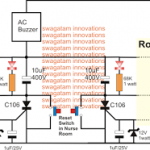
A simple Transcutaneous Nerve Stimulator Circuit may be witnessed in the above figure, using the work horse IC 555 configured in its standard astable mode
P1 is used for producing several ranges of frequency outputs in conjunction with a variations in the pulse widths of the output frequency for the implementing the above explained TENs procedures T1 is used for producing TENs at the level of the supply voltage for acquiring maximum effectiveness.
The transformer could be any ordinary radio output audio transformer or made by winding 10:100 turns 36 SWG super enameled wire on a small EE ferrite core.
The output of the transformer could be arranged in the form tiny protruding copper prods, not too sharp but sufficient enough for creating a slight digging impression on the skin and may be wrapped on the affected area with some suitable cohesive band.
2) TENS Circuit for Multiple Nerve Stimulation
The following circuit was requested by one of the dedicated visitors of this blog, as given below:
"I am looking for a circuit solution to perhaps utilize a pair of bar/dot graph display IC's and to take each triggered output and transform this output to a voltage sufficiently high to stimulate nerve endings .
The nerve endings are connected via a conductive needle ( stainless steel) making intimate contact with said nerve endings. I have suffered by convulsive 'jumping' of my legs when I relax and when I am in bed.
I have been to a number of specialists without them being of any assistance. I have been reading about T.E.N.S. and believe that this could be worthy of an experiment. There are apparently many people world wide suffering from this complaint.
My thoughts are that if I feed a variable signal of low amplitude into the nerve ending that the continual low stimulation might override the large pulses which cause instant muscle contraction. I believe that this is worth a try."
Circuit Diagram
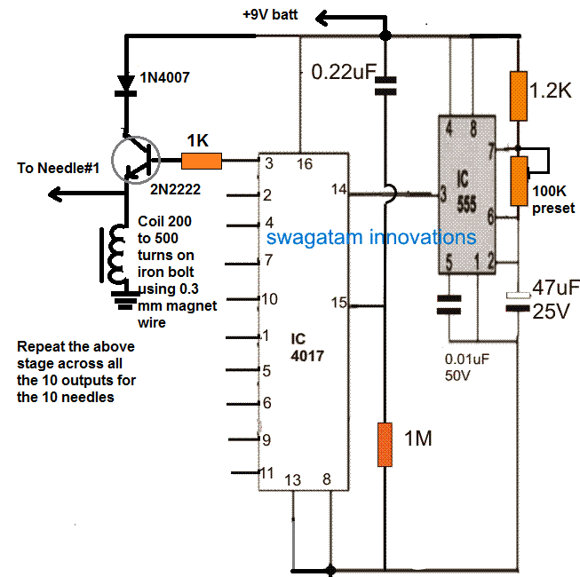
The circuit is based on a simple IC 4017 and IC 555 sequential dot mode driver circuit. The output of the IC 4017 create a running or sequencing high logic pulse across its 10 outputs in response to the clocks generated by the IC 555 astable at its pin#14. Each of these outputs are configured across a transistor/inductor circuit which act like a small boost converters, and convert the 9V pulse into a low current 100V or 120V short pulses.
The indicated ends could be integrated with 10 individual needles for the required transcutaneous stimulation across the intended muscle areas.
The pulse width and frequency can be controlled by adjusting the 100k preset.
Warning: The coil dimension and voltage presented above are assumed values only, and have not been confirmed. Serious experimentation may be required through qualified medical engineers before implementing the device practically.


Comments
Hello sir how are you khalid here hope you are fine. I make first circuit with ic 555 i made small transformer from mobile charger i removed its winding and put 100 tons and 10 tons for output and i used this for the first circuit the transister getting warm but on the probes i dont feel any anything .i checked ic pin3 getting around 7v volts.so how to know the circuit is working .i need your help please reply thanks.
Hello Khalid, are you sure the IC is oscillating correctly? Please disconnect the transformer and check the collector side with an LED/1k, and by changing the C1 to 100uF…if the LEd blinks then your IC 555 is working OK, and you can then restore back the earlier configuration.
By the way a 10:100 might not be enough, you may have to try a 10:500 configuration for getting a jolt at the secondary side.
Hello sir khalid here i checked led with 10k its working continue not blinking and on collecter there voltage 0.107 is this enough for transformer to work or ic may faulty because pin3 of 555 ic giving 7.5 volts and when i remove transformer there is voltage on collecter but only 0.107 when i connect transformer collecter bemes zero volt so what can be the problem i make 500tons on primary and secondary 10tonnes .please i need your help waiting for reply thanks.
Hi, Please let me know that Normal pulse generator circuit by 555 ic can be used instead of this? I mean is it possible to use Pulse generator circuit and replace the LED with the winding?
Hi, the above circuit is a normal IC 555 pulse generator and therefore any similar circuit can be used…but since it is a medical equipment I can’t suggest much, better confirm from a professional in the field…there’s no led in the circuit
Dear Swagatam, I have a requirement.
A deaf mute boy I know is finishing college and about to take a job. He fails to feel the vibration of his phone or alarm clock frequently, and this causes problems for him. I want to design a ‘shock alarm’ for him to connect to his phone (either wired through the earphone socket or blue tooth will do) which will make him aware, he can then text the caller. I was thinking of tweaking a nerve stimulator for the purpose. Your ideas please? Thanks in advance. I am a doctor by profession, a DIY enthusiast and a big fan of your creations.
Thank you Dr Vishwanath, I think this can be solved through a cheap bluetooth headset device. We can modify it by eliminating its earphone, and terminating the end wires through capacitors, such that the ends of the capacitors touch the boy’s skin.
Once the device is paired with the phone, the ringtone will connect with the bluetooth, and activate the wire ends with minute oscillating current which will create a tingling sensation on the boy’s skin alerting him regrading the phone call.
Let me know if you have further questions, and I am glad you liked my website and the posts.
Is That Works?
And Where To Put Electrodes?
Any Video?
Hey, Last Year For My Annual Project Exhibition I made The Drip Indicator following your site.
For this year want you to refer me something like new and rare.
Glad my projects are helping you. If you can hint the field of application, I may try suggesting an idea.
Many Thanks swag, I will build this circuit and have a play, I will lwt you and your readers know the results. cheers, Tapadh leat Ken
Thanks Ken, wish you all the best!! Cheers
Olá Swagatam, bom dia.
Estou realizando este circuito porem apareceu uma duvida no trafo ( 10: 100 voltas 36 SWG).
Quantas voltas no primario?
Quantas voltas no secundario?
Qual fio usar?
Agradeço se puder me ajudar
Oi Joao, aqui 1 significa aproximadamente igual à tensão de alimentação, então se a sua tensão de alimentação for 12, você pode usar 12 enrolamentos para o lado mencionado 1 e 12 x 10 para o lado mencionado 10