There are many cases where it is desirable to actively regulate the operating temperature of an electronic assembly. Sometimes, it is imperative to dissipate the heat generated by the components (this is the case for the majority of microprocessors in our modern PCs). On the contrary, it is necessary to artificially increase the operating temperature of a system to increase the stability of some of its characteristics (the frequency of a quartz oscillator, for example).
We propose to carry out two simple circuits that will help you effectively solve the two temperature regulation problems that we have just mentioned.
Our two implementations use a temperature sensor to determine the desired operating point.
About LM335 Sensors
We have selected a widely used sensor that is still distributed in a non-SMT package (TO92 package, in our case). It is the LM335 sensor.
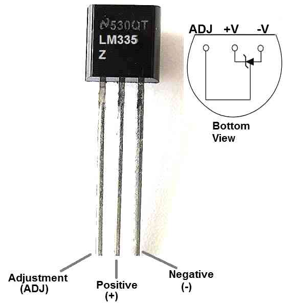
The LM135 or LM235 sensors are also suitable, but they are generally a bit more expensive. The LM335Z is characterized by a nominal voltage at its terminals that is proportional to the absolute temperature of its package (temperature expressed in °K).
It is calibrated to develop a voltage of 10 mV/°K, in a range of use ranging from -40 °C (233.15 °K) to +100 °C (373.15 °K).
Recall that the zero of absolute temperature (expressed on a dynamic or absolute scale whose unit is the Kelvin degree) is shifted by -273.15 degrees compared to our usual temperature scale (Celsius scale).
The conversion from one scale to the other is easily done using the following relation:
T(°C) = T(°K) +273.15.
If we apply this relation to the output voltage of our LM335 temperature sensor, we obtain:
V(T)= 2.7315 +(T x 10 mV/°C)
Here, V is expressed in volts and T in C.
For example, when the ambient temperature of the sensor package is +25 °C, the voltage present at its terminals is about 2.98 V.
The proportionality of the output voltage with respect to the absolute temperature of the package makes the LM335 sensor very easy to use, as you can see for yourself in the diagrams reproduced in figures 1 and 2.
How the Temperature Regulator Works
The diagram in figure 1 represents a small temperature control system using ventilation, while figure 2 shows a small temperature control system using heating resistors. As you can see, the two diagrams are almost identical, except for the detection polarity.
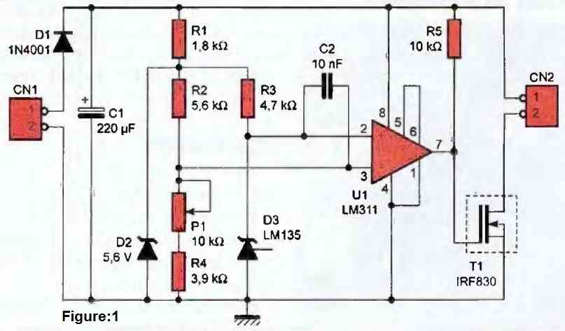
In the case of the diagram in figure 1, the voltage developed by the temperature sensor (D3) is compared by the U1 circuit via its positive pin (2) to a reference voltage applied to its negative pin (3).
When a voltage at the terminals of the temperature sensor exceeds the reference voltage (i.e., when the temperature of the sensor increases), the output of comparator U1 goes high, which biases MOS transistor T1 into saturation mode. This triggers the fan that is connected to connector CN2.
Note that the transistor chosen for this circuit can switch a current of up to 3 A, which is widely oversized to drive most 12 V fans to which our circuit is intended.
Effect of Fan
Note that with our diagram, the power limitation of the fan is rather dictated by the possibilities of diode D1 (do not exceed 1 A with this diode). That said, let's get back to our main explanation.
Under the effect of the fan (feel free to position the fan and sensor close to the system whose temperature you want to regulate), the temperature of sensor D3 will decrease, causing a simultaneous decrease in the voltage developed at its terminals.
If the fan is properly sized, the temperature of the sensor drops below the threshold for which the voltage at its terminals is lower than the reference voltage. Then, the output of comparator U1 falls to zero, causing T1 to be blocked and the fan to stop.
Under the effect of the heat dissipated by the surrounding systems, the temperature of the sensor quickly increases again, causing a new cooling cycle.
In the end, the temperature oscillates significantly around the threshold for which the fan is activated, ensuring a suitable regulation of the temperature of the systems placed near the fan (provided that the ventilation system is properly sized in relation to the heat to be dissipated).
The assembly is designed to operate from 9 V to 12 V, via a power supply connected to CN1. The supply voltage does not need to be regulated, but it must be properly filtered. A small power supply capable of providing the necessary current to the fan, with an overload of 50 mA, is sufficient. Diode D1 protects the assembly in case of reverse polarity of the power connector, while zener diode D2 maintains a relatively insensitive reference voltage to variations in the supply (however, this is not the case for the fan speed).
Variable resistor P1 allows the reference threshold to be set, which determines the desired temperature. Capacitor C2 filters out parasitic oscillations from the assembly, knowing that the comparator is mounted here without hysteresis. The natural hysteresis of the comparator is sufficient for our application, knowing that the stability of our regulation loop depends essentially on the properties of the temperature sensor and the performance of the ventilation system.
To finish describing the circuit diagram in Figure 1, the output of comparator U1 is an open collector output, hence the presence of resistor R5 to correctly bias MOS transistor T1 when the comparator switches to the high state.
Heat Generation and Regulation
Now let's move on to the circuit diagram in Figure 2, which is very similar to the previous one, but whose purpose is completely reversed compared to the circuit in Figure 1.
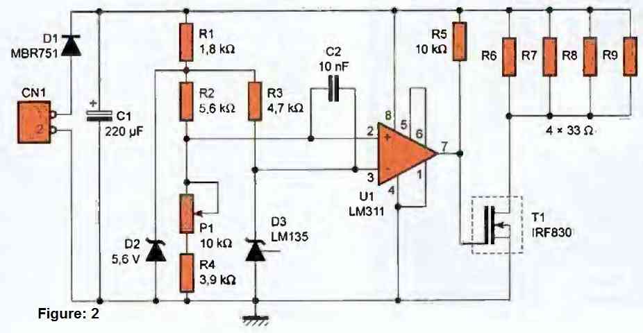
This time, the circuit no longer drives a fan but heating resistors of 33 Ω (R6 to R9) designed to raise the ambient temperature of the system in which this circuit will be placed.
The reference voltage and the temperature sensor voltage have changed input to the comparator, which reverses the direction of the control loop.
Transistor T1 is now conducting as long as the sensor temperature is below the threshold set by the adjustable resistor P1. Under the effect of the power dissipated by resistors R6 to R9, the ambient temperature will rise until the voltage developed by the sensor is sufficient.
Increased Temperature for Quartz Oscillators
This temperature regulation mode is commonly used to ensure very high stability on quartz oscillators. The operating point is generally chosen a few degrees above the maximum ambient temperature. Around 40°C to 50°C may be sufficient in temperate regions, but 60°C to 70°C are preferable for better operating margins in difficult environments, such as behind the windshield of a vehicle parked in full sun.
It goes without saying that resistors R6 to R9 and sensor D3 must be confined with the system whose temperature needs to be regulated. Enclosure is generally a bit more delicate and it is common to limit thermal confinement to the strict minimum. You will therefore likely need to place the resistors and sensor remotely.
To offer you a little more latitude in the choice of resistors R6 to R9 (depending on the volume to be heated), we have changed diode D1 for this circuit. Thus, at 12 V, you can "drive" resistors ranging from 33 Ω (4 W) to 22 Ω (6.5 W), which should be sufficient for many applications (after all, this still represents 4 x 6.5 W dissipated, not to mention losses in T1).
Caution
We draw your attention to the risks of burning that may occur with this heating system, if the control is set to maximum position. Furthermore, in case of failure of the system (for example, in case of a short circuit on T1 or if the resistance P1 is open), the temperature reached by the entire system could lead to a risk of fire (depending on the overall dimensions of the system, thermal resistance, the nature of the materials used, the environment in which the system is used, etc.). Therefore, avoid oversizing the heating resistors compared to the volume you need to heat and refuse to use such a system in unmonitored areas.
To assess the risks of dangerous oversizing of the system, you can simulate the effects of a control failure on the final system (in its real working environment) by removing the adjustable resistor P1 from the system. By measuring the internal temperature of the system for a sufficient amount of time, you can determine the open-loop asymptote of your system and judge whether there is a risk of system fire (depending on the materials used) in case of a control failure. Readers are strongly advised to exercise caution regarding the implementation conditions and sizing of this system, which remain their sole responsibility.


Need Help? Please Leave a Comment! We value your input—Kindly keep it relevant to the above topic!