In this post I have explained 4 easy to build, compact simple transformerless power supply circuits. All the circuits presented here are built using capacitive reactance theory for stepping down the input AC mains voltage. All the designs presented here work independently without any transformer, or no transformer. The Transformerless Power Supply Concept As the […]
Explained
How to Sense Current Using Op-Amp: Low Side and High Side Circuits Explained

In this post we are going to learn one very interesting and also very much useful topic that is how we can measure the current which is going through any load by just using some normal resistors and one op amp circuit. We know already that current is one very important thing in every electrical […]
3 Sound Activated Switch Circuits Explained

In this post I have explained 3 simple sound activated relay switch circuits which can used as a module for any system that might be assigned to trigger by detecting some kind of sound pressure level. Or simply applications such as a voice activated alarm security circuit. 1) Circuit Objective Utilizing this basic sound activated […]
How to Build a Boost Converter Circuit: Explained with Calculations
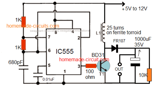
I have explained comprehensively how to build a boost converter circuit for converting a low level DC voltage inputs to a higher level DC voltage outputs. I have furnished all the required calculations s that you can design a customized boost converter circuit. A Practical Boost Converter Circuit Design using IC 555 This simple circuit […]
Explained: Snubber Circuit for MOSFET H-Bridge

Here we are going to talk deeply about snubber circuits and why we must use them with MOSFET H-bridge circuits. Because if we do not put snubber in H-bridge then that MOSFETs might blow off during switching. Specially when we drive inductive loads like transformer, motor, relay, solenoid, etc. then this thing becomes very serious. […]
Reed Switch Sensor Module Explained with Circuit Diagram
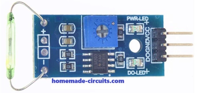
Here we will try to understand this reed switch sensor module which may look small and nothing much, but it is actually very useful thing when we want to detect a magnetic field or just want to know if a magnet is coming closer or going away. This thing is called a reed switch sensor […]