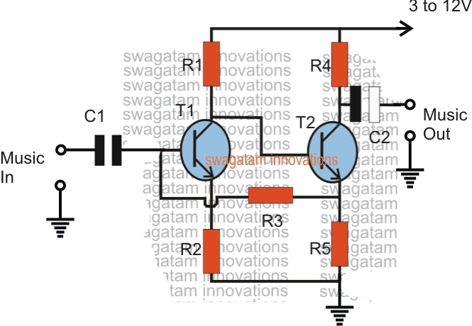
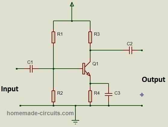
As the name suggests a preamplifier circuit pre-amplifies a very small signal to some specified level that can be further amplified by an attached power amplifier circuit. It basically acts like a buffer stage between the input small signal source and a power amplifier. A preamplifier is used in applications where the input signal is […]
Explained
4 Efficient PWM Amplifier Circuits Explained
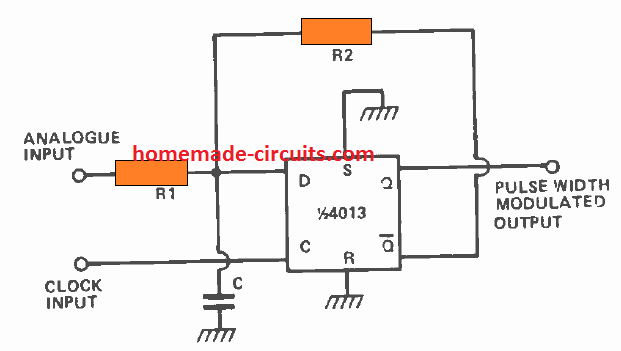
Audio amplifiers which are designed to amplify an analogue audio signal through pulse width modulation or PWM processing and with adjustable duty cycle is known by many names including digital amplifier, Class-D amplifier, switched amplifier and PWM amplifier. (Article Contributed by: Ritu khanna) Because it can perform at high efficiencies, a Class-D amplifier has become […]
Types of Power Amplifier Classes Explained in Simple Words
In this post I am going to explain power amplifiers and their classification according to their output electrical characters and application. We will be exploring amplifier classes: A, B, AB, C, D, E, F, G, H, I, S and T briefly and yes, that’s a lot of amplifier types that are available in today’s electrical […]
Audio Clipper and Compressor Circuits Explained
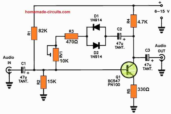
In this article I have explained using circuit diagrams how a clipper and a compressor circuits work to processes an input audio signal as per the required output signal. What is an Audio Clipper An audio clipper circuit is basically used to alter or restrict the amplitude (volume) of an audio signal. There are mostly […]
Explained: MAX4466 Electret Microphone Amplifier Module with Adjustable Gain
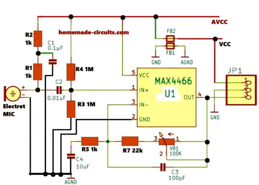
In this post we will be talking about this MAX4466 microphone amplifier module, right? So this is a tiny little circuit that can amplify weak sound signals from an electret condenser microphone (ECM). That means it is going to take a very small electrical signal from the microphone and then boost it up so we […]
OCL Amplifier Explained
In the field of audio amplifiers OCL stands for Output Capacitor-Less Amplifier design. How it Works In this OCL type of amplifier topology or configuration, the power output stage is directly coupled to its preceding driver stage without coupling capacitors. The following figure shows a typical OCL amplifier output stage, as can be seen, the […]