In an op amp oscillator circuit, an op amp is configured with a resistor-capacitor feedback loop or a inductor-capacitor feedback loop, which triggers the op amp to go into an oscillating mode, generating a switching ON/OFF pulses from its output pin. The high-gain and wide passband of operational amplifier (op amp) ICs makes it possible […]
Explained
5 Useful Motor Dry Run Protector Circuits Explained
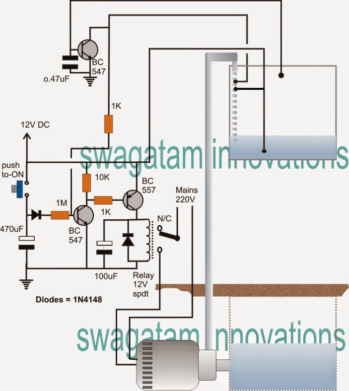
The 5 simple dry run protector circuits presented here shows simple methods by which insufficient water conditions inside an underground tank can be sensed without introducing probes inside the underground tank, and thus preventing any possibility of motor dry running. The circuit also incorporates an overhead water overflow control feature. The idea was requested by […]
Simple Electronic Dog Whistle Circuit Explained
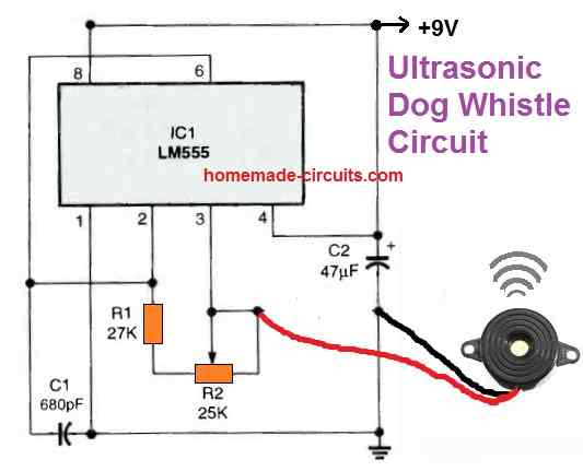
An electronic dog whistle is a device that generates ultrasonic sound waves and is used for training dogs and for controlling excessive barking habit. Because dogs and domestic cats can hear ultrasonic frequencies, humans cannot, this dog whistle device is employed to train these animals. It is also sometimes known as a silent whistle or […]
Force Sensing Resistor Circuit Explained
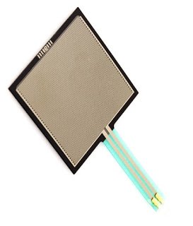
In this article we are going to see, what force sensing resistor is, their construction, specification and finally how to interface it with Arduino microcontroller. We will also study a couple of comparator circuits based on 741 and LM311 ICs, for operating a relay using force sensitive resistor. What is Force Sensing Resistor A force […]
Different Types of UPS systems – Explained
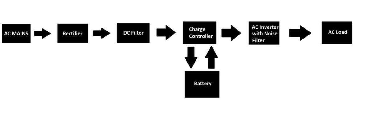
In this post I am going to explain different types of uninterruptible power supply (UPS) that are available in the market and how they are classified according to the consumer’s requirement. We will also explore the different types of UPS’s block diagram to understand their technical difference between them. UPS systems are a type of […]
Simple Delay Timer Circuits Explained
In this post I have explained the making of simple delay timers using very ordinary components like transistors, capacitors and diodes. All these circuits will produce delay ON or delay OFF time intervals at the output for a predetermined period, from a few seconds to many minutes. All the designs are fully adjustable. Importance of […]