In this post I will show how to construct a SMS based water pump controller with automatic shutdown of pump when no water flow through the pump is detected. We will also construct another much simpler automatic dry run preventer circuit without GSM in the next half of the article.
What is Dry Run in Motors
We have already discussed on GSM based pump controller on this website check it out if haven’t yet. Here we are adding an additional feature on existing design, which will prevent the motor from dry running.
Dry running means running the water pump without liquid flow. The consequence can be serviceable damage to unserviceable damage depending on how long the motor was running without pumping the water and the quality of the water pump.
Yes, the water pumps are not cheap and if you are an agriculturist who irrigate the field every day, then a small issue with your water pump can land you in economic loss.
Servicing the pump may take some time and money, so it is better to follow the famous slogan “prevention is better than cure”.
Motor dry run is a very common problem, when there is not enough water to flow through the pump, over heating of mechanical components as well as electrical components will occur.
At a point the mechanical components will start to melt and also may cause short circuit.
Such disaster may be prevented using the circuit, proposed in this project.
To detect the flow of water, we are utilizing YF-S201 water flow sensor. When no water flow is detected by the sensor, it cuts off the power supply to water pump and send an SMS acknowledgement to the recipient about the dry run shut off.
With this GSM based control you can turn on and off the pump and also the circuit acknowledges about the pump dry run issue.
Circuit for SMS based pump control:
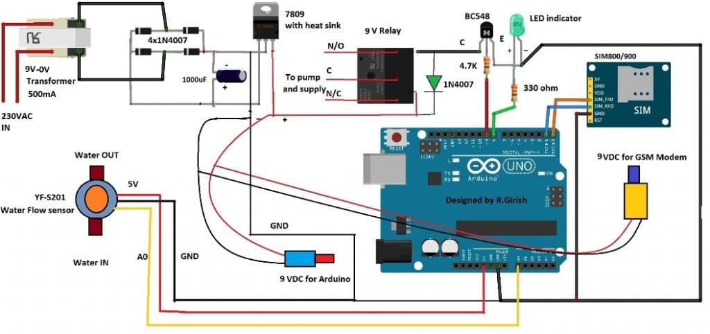
The circuit consists of AC to DC converter using 9V transformer, bridge rectifier a smoothing capacitor of 1000 uF and a LM7809 9V regulator. Two DC jacks are provided for powering Arduino board and SIM 800 / SIM 900 GSM module.
Never power the GSM module with 5V pin of Arduino to 5V pin of GSM module as the Arduino board cannot provide enough current.
The connection between Arduino and GSM module as follows:
Arduino TX ---------------------- RX SIM 800 / 900
Arduino RX --------------------- TX SIM 800 / 900
Arduino GND ------------------- GND SIM 800 / 900
The main supply is provided by the LM 7809 regulator.
The LED indicator will glow if the relay is activated and turns off when the relay is deactivated.
The diode IN4007 will absorbed high voltage spike which occurs while switching the relay on and off.
The water flow sensor is connected to A0 pin of Arduino, 5V and GND provided from Arduino board.
Program for GSM based design:
/* Improved Version of SMS Based Pump Controller Code */

int motor = 8;
int LED = 9;

const int flowInput = A0;
const int testPin = 6;

bool motorON = false;

char str[30];
byte indexPos = 0;

const char PHONE[] = "+91XXXXXXXXXX";   // <--- PUT NUMBER HERE

void setup() {
  Serial.begin(9600);

  pinMode(motor, OUTPUT);
  pinMode(LED, OUTPUT);

  digitalWrite(motor, LOW);
  digitalWrite(LED, LOW);

  analogWrite(testPin, 100);

  delay(5000);   // short delay only

  sendCommand("AT+CNMI=2,2,0,0,0", 1000);
  sendCommand("AT+CMGF=1", 500);

  sendSMS("System is ready to receive commands.");
}

void loop() {
  readSMS();

  if (motorON) {
    checkDryRun();
  }
}

void readSMS() {
  while (Serial.available()) {
    char c = Serial.read();

    if (c == '/') {
      indexPos = 0;         // start of message
    }

    str[indexPos++] = c;
    if (indexPos >= 29) indexPos = 29;
    str[indexPos] = '\0';

    if (c == '/') {         // end of message
      processCommand();
      indexPos = 0;
      str[0] = '\0';
    }
  }
}

void processCommand() {
  if (strstr(str, "/motor on/")) {
    digitalWrite(motor, HIGH);
    digitalWrite(LED, HIGH);
    motorON = true;
    sendSMS("Motor Activated");
  }

  else if (strstr(str, "/motor off/")) {
    digitalWrite(motor, LOW);
    digitalWrite(LED, LOW);
    motorON = false;
    sendSMS("Motor Deactivated");
  }

  else if (strstr(str, "/test/")) {
    sendSMS("The System is Working Fine.");
  }
}

void checkDryRun() {
  unsigned long highPulse = pulseIn(flowInput, HIGH, 200000);
  unsigned long lowPulse  = pulseIn(flowInput, LOW, 200000);

  if (highPulse == 0 || lowPulse == 0) {
    digitalWrite(motor, LOW);
    digitalWrite(LED, LOW);
    motorON = false;

    sendSMS("Motor Deactivated. Dry Run Shut Off!");
  }
}

void sendCommand(const char *cmd, int d) {
  Serial.println(cmd);
  delay(d);
}

void sendSMS(const char *msg) {
  Serial.print("AT+CMGS=\"");
  Serial.print(PHONE);
  Serial.println("\"");
  delay(500);

  Serial.println(msg);
  delay(100);

  Serial.write(26);     // CTRL+Z
  delay(1500);
}
Here is the tested SMS while prototyping:
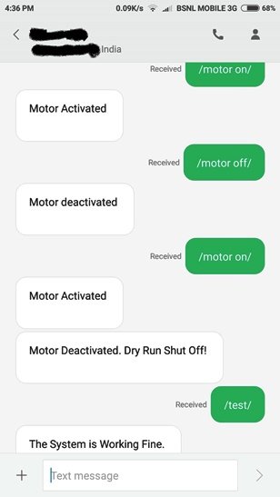
The following things we can observe from the screen shot:
· First the motor is turned on and the circuit acknowledged with a reply.
· The motor is deactivated and the circuit is acknowledged with a reply.
· Again the motor is activated and unplugged the sensor to simulate dry run situation, the circuit turns the pump off and replied with pump dry run acknowledgement.
· Finally a test SMS has sent and the circuit replied with “System is Working Fine”.
I would suggest installing the water flow sensor after couple of meters after the water pump.
That concludes the GSM based pump dry run preventer.
Now let’s take a look at simple water pump dry run preventer without GSM, this could be the easier of the two.
Circuit Diagram:
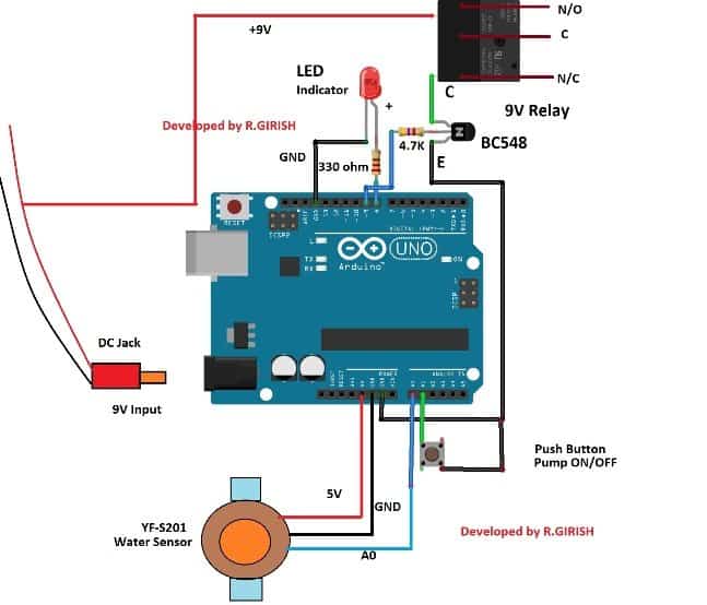
Nothing much about to explain here, just wire up as per the schematic. The power supply can be a 9V wall adapter with at-least 500 mA or the supply which illustrated in the GSM based controller schematic.
The push button is provided to turn the pump on and off.
Once you press the button to turn on the pump, the circuit waits till 20 seconds initially to detect the flow of water, during that time the push button is disabled for 20 seconds.
After the initial 20 seconds the push button is enabled and you may turn OFF the pump manually by pressing the push button again.
If water flow is detected the circuit keeps the pump ON after 20 seconds, otherwise the circuit cuts the power supply to the motor. Also the circuit can cut off the supply at any instant, if no water flow detected.
If the circuit shut off due to dry run, the LED blinks rapidly.
Program for simple pump dry run preventer:
/* Improved Simple Pump Dry Run Preventer Code */

int X = 0;
int Y = 0;

bool motorOn = false;
bool buttonState = HIGH;
bool lastButtonState = HIGH;

unsigned long lastDebounce = 0;
unsigned long debounceDelay = 50;

const int inputPin  = A0;
const int testPin   = 6;
const int buttonPin = A1;
const int LED       = 8;
const int motor     = 9;

void setup() {

  Serial.begin(9600);

  pinMode(inputPin, INPUT);
  pinMode(testPin, OUTPUT);
  pinMode(buttonPin, INPUT_PULLUP);
  pinMode(LED, OUTPUT);
  pinMode(motor, OUTPUT);

  analogWrite(testPin, 100);

  digitalWrite(LED, LOW);
  digitalWrite(motor, LOW);
}

void loop() {

  handleButton();

  if (motorOn) checkDryRun();
}

void handleButton() {
  int reading = digitalRead(buttonPin);

  if (reading != lastButtonState) {
    lastDebounce = millis();
  }

  if ((millis() - lastDebounce) > debounceDelay) {
    // actual button press detected
    if (reading == LOW && buttonState == HIGH) {
      toggleMotor();
    }
    buttonState = reading;
  }

  lastButtonState = reading;
}

void toggleMotor() {
  if (!motorOn) {
    Serial.println("Motor Activated");
    digitalWrite(LED, HIGH);
    digitalWrite(motor, HIGH);
    motorOn = true;
  } else {
    Serial.println("Motor Deactivated");
    digitalWrite(LED, LOW);
    digitalWrite(motor, LOW);
    motorOn = false;
  }
}

void checkDryRun() {

  X = pulseIn(inputPin, HIGH, 200000);
  Y = pulseIn(inputPin, LOW, 200000);

  if (X == 0 || Y == 0) {
    Serial.println("Dry Run Detected - Motor Shut Off");
    digitalWrite(motor, LOW);
    digitalWrite(LED, LOW);
    motorOn = false;

    // Blink LED for warning but allow restart
    for (int i = 0; i < 10; i++) {
      digitalWrite(LED, HIGH);
      delay(300);
      digitalWrite(LED, LOW);
      delay(300);
    }
  }
}
That concludes the both the designs.
If you have any specific questions regarding this SMS based pump controller with automatic dry run shut down circuit, please express in the comment section, you may receive a quick reply.


Comments
Hello Sir. I have a project: “INTELLIGENT GLASS SYSTEM FOR THE BLIND” I need a Camera to capture images, send them to a server and Optical Character Recognition (OCR) work to convert the text into audio feedback. The audio is then relayed back to the user, allowing them to ‘read’ text through sound via a speaker. All this should be done offline. I have found that at least no arduino is capable of such.
what should I do Sir?
Thank you.
Hello Jedidiah,
The idea looks very good and innovative, but it seems to be beyond the level of my expertise, I have no idea how to handle the server transmission and the related parameters.
i had connected all the connections but motor starts as soon as give the supply to ckt i (is the relay connections right i think it should to n/o)
please check it by swapping the relay contact, check it with a bulb first, if everything works then you can connect the actual load.
Hello Sir,
is there any other ways to check the pump is running in dry state or not. I heard that few industrial dry run sensor are actually calculating voltage difference or amp difference when pump is in normal vs in dry state.
Hi Madhav, Checking the amp difference is the best and the most reliable way according to me…another way is by monitoring motor temperature
Thanks for the replay Sir,
How can monitor the same, I mean is there any we can input the current amp feed to arduino and analysing it take action.
Thanks in advance .
Madhav, monitoring it through wireless method can be a lot complicated, however an arrangement can be made where the motor will be automatically switched OFF and an SMS sent to your mobile regarding the same..
i want to learn to code the arduino UNO board i recently purchased. this is some thing i want to do before i die. i am 80 years old. so if you can help u better hurry. many thanks in advance.
I wish I could teach you, however I am myself in the learning stages of Arduino so cannot provide much help, nevertheless If possible i’ll try to publish a related post which will help understanding Arduino easier for all the interested readers like you
much obliged. God Bless, Fali
Help me sir I want both sms and call control 3 phase water pump with automatic dry shut off I’m farmer I’m try to this project my own farm plzz sir help me
Hi Rushikesh, you can use the same circuit and code and build it for your 3 phase motor.
The only change you need to implement is:
Replace BC548 with a TIP122, and replace the single relay with three 30 amp relays in parallel (coils in parallel)…the 1N4007 can be a common diode for all the 3 coils in parallel.
After this you can wire the 3 separate contacts of the relay with the 3 wires of the 3 phase motor.
Alternatively you can replace the relay with a single TTTP relay or a triple throw triple contact relay (30 amp)
thank u for ur reply sir, but pls wot is d value of c1, c2, c3 d1, d2 in d above 555 voltage doubler if i want to use it to power 35v from 12v or 15v transformer.
you can use C1 = 0.1uF, C2, C3 = 100uF/25V, D1, D2 = 1N4007
pls sir can i power 35v dc from 15v or 12v transformer by using voltage doubler. and pls can u give me d circuit diagram of d voltage doubler i am suppose to use in dat situation. tnx
wireless, yes you can do that by using the circuit explained in the following links:
https://www.homemade-circuits.com/?s=voltage+doubler