If you are looking for an option to replace conventional welding transformer, the welding inverter is the best choice. Welding inverter is handy and runs on DC current. The current control is maintained through potentiometer.
By: Dhrubajyoti Biswas
Using Two Switch Topology
When developing a welding inverter, I applied forward inverter with two switches topology. Here the input line voltage traverses through the EMI filter further smoothing with big capacity.
However, as the switch-on current pulse tends to be high there needs the presence of softstart circuit. As the switching is ON and the primary filter capacitors charges via resistors, the power is further zeroed by turning the switching ON the relay.
The moment the power is switched, the IGBT transistors gets used and are further applied through TR2 forward gate drive transformer followed by shaping the circuit with the help of IC 7812 regulators.
Using IC UC3844 for PWM Control
The control circuit used in this scenario is UC3844, which is very much similar to UC3842 with pulse-width limit to 50% and working frequency to 42 kHz.
The control circuit draws the power from an auxiliary supply of 17V. Due to high currents, the current feedback uses Tr3 transformer.
The voltage of 4R7/2W sensing register is more or less equal to the current output. The output current can be further controlled by P1 potentiometer. Its function is to measure the feedback’s threshold point and the threshold voltage of pin 3 of UC3844 stands at 1V.
One important aspect of power semiconductor is that it needs cooling and most of the heat generated is pushed out in output diodes.
The upper diode which consists of 2x DSEI60-06A should have the capacity to handle the current at an average of 50A and loss till 80W.
The lower diode i.e. STTH200L06TV1 also should the average current of 100A and loss till 120W. On the other hand, the total max loss of the secondary rectifier is 140W. The L1 output choke is further connected with the negative rail.
This is a good scenario since the heat sink is barred from hi-frequency voltage. Another option is to use FES16JT or MUR1560 diodes.
However, it is important to consider that the max current flow of the lower diode is twice the current to that of the upper diode.
Calculating IGBT Loss
As a matter of fact, calculating IGBT’s loss is a complex procedure since besides conductive losses switching loss is another factor too.
Also each transistor loses around 50W. The rectifier bridge also loses power till 30W and it is placed on the same heat sink as IGBT along with UG5JT reset diode.
There is also the option to replace UG5JT with FES16JT or MUR1560. The loss of power of the reset diodes is also dependent upon the way Tr1 is constructed, albeit the loss is lesser compared to the loss of power from IGBT. The rectifier bridge also accounts to power loss of around 30W.
Furthermore when preparing the system it is important to remember to scale the maximum loading factor of the welding inverter. Based upon the measurement, you can then be ready to select the correct size of the winding gauge, heat sink etc.
Another good option is to add a fan as this will keep a check on the heat.
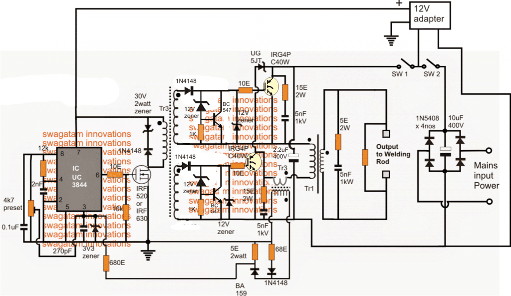
Circuit Diagram
Transformer Winding Details
The Tr1 switching transformer is wounded two ferrite EE core and they both have the central column section of 16x20mm.
Therefore, the total cross section calculates to 16x40mm. Care should be taken to leave no air gap in the in the core area.
A good option would be to use 20 turns primary winding by wounding it with 14 wires of 0.5mm diameter.
The secondary winding on the other hand has six copper strip of 36x0.55mm. The forward drive transformer Tr2, which is designed on low stray inductance, follows trifillar winding procedure with three twisted insulated wire of 0.3 mm diameter and the windings of 14 turns.
The core section is made of H22 with the middle column diameter of 16mm and leaving no gaps.
The current transformer Tr3 is made of EMI suppression chokes. While the primary has only 1 turn, the secondary is wounded with 75 turns of 0.4 mm wire.
One important issue is to keep the polarity of the windings. While L1 has ferrite EE core, the middle column has the cross section of 16x20mm having 11 turns of copper strip of 36x0.5mm.
Furthermore, the total air gap and the magnetic circuit are set to 10mm and its inductance is 12uH cca.
The voltage feedback does not really hamper the welding, but it surely affects the consumption and the loss of heat when in idle mode. The use of voltage feedback is quite important because of high voltage of around 1000V.
Moreover, the PWM controller is operating at max duty cycle, which increases the power consumption rate and also the heating components.
The 310V DC could be extracted from the grid mains 220V after rectification via a bridge network and filtration through a couple of 10uF/400V electrolytic capacitors.
The 12V supply could be obtained from a ready-made 12V adapter unit or built at home with the help of the info provided here:
Aluminum Welding Circuit
This request was submitted to me by one of the dedicated readers of this blog Mr. Jose. Here are the details of the requirement:
My welding machine Fronius-TP1400 is fully functional and I have no interest in changing its configuration. This machine that has an age is the first generation of inverter machines.
It is a basic device for welding with coated electrode (MMA welding) or tungsten arc gas (TIG welding). A switch allows the choice.
This device only provides DC current, this is very appropriate for a large number of metals to be welded.
There are a few metals such as aluminum that due to its rapid corrosion in contact with the environment, it is necessary to use pulsating AC current (square wave 100 to 300 Hz) this facilitates the elimination of corrosion in cycles with inverted polarity and turn the melting in the direct polarity cycles.
There is a belief that aluminum does not oxidize, but it is incorrect, what happens is that at the zero moment that it receives contact with air, a thin layer of oxidization is produced, and which from then on preserves it from next subsequent oxidization. This thin layer complicates the work of welding that's why AC current is used.
My desire is make a device that be connected it betwen the terminals of my DC welding machine and the Torch to obtain that AC current in the Torch.
This is where I have difficulties, at the moment of building that CC to AC converter device. I am fond of electronics but not expert.
So I understand the theory perfectly, I look at the HIP4080 IC or similar datasheet seeing that it is possible to apply it to my project.
But my great difficulty is that I do not do the necessary calculation of the values of the components. Maybe there is some scheme that can be applied or be adapted, I not find it on internet and I do not know where to look, that's why I ask for your help.
The Design
In order ensure that the welding process is able to eliminate the oxidized surface of an aluminum and enforce an effective welding joint, the existing welding rod and the aluminum plate could be integrated with a full bridge driver stage, as shown below:
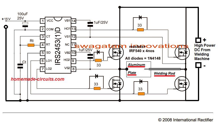
The Rt, Ct could be calculated with some trial and error to get the mosfets oscillating at any frequency between 100 and 500Hz. For the exact formula you could refer to this article.
Th 15V input could be supplied from any 12V or 15V AC to DC adapter unit.

Comments (144)
would I be correct in assuming that this circuit (welding circuit) could be applied to a higher current mosfet module such as the vishay VS-FC420SA15?
And if I wanted to make a frequency display, it could be taken from any of the drive outputs of the IRS2453, but would be half the frequency of the inverter circuit?
I’ve downloaded the data sheet for the IRS2453, but it does not show these details..
Thanks for the reply, so the next question would be;
Has anyone successfully implemented this design as a square-wave DC welder add-on , or is it all theoretical “looks good on paper”?
Yes, if the MOSFETs are rated appropriately, then it can be used with the above design.
For the frequency measurement I think you can try it across the Ct capacitor of the IC…
sir why did my inverter produce high current and refuse to be controlled
gracias por toda esa información.
Dear Sir,
Can you send the schematic diagram for Intimax inverter welder machine model no BEST 310.
Thank your valuable support.
is that working sir ?
it is working, but recommended only for the experts in the field…
is it possible to make 60volt 20 amps SMPS with this design? thnx.
it is possible…
sempre estudo os seus circuitos. sao inovadores e faceis de entender. obrigado por compartilhar conhecimento
Thank you so much Wilson, glad you found my circuits helpful!
Sir will a field stop igbt with 600v and 40 amp rating work as I am not able to find the stated igbt in the circuit diagram
Shantanu, I think it should work, however it is recommended to use the one that is stated in the diagram.
Very good share
Hi
how are you I hope you are doing fine.
sir I have a question, and my question is ; what are the problems that caused the out put failure for the igbt inverter welding machine, and as a layman what’s the solution to the problems ?
Thank you sir!
Hi Sani,
IGBT can fail due to overload, over current and avalanche voltage issues. The solution is to implement appropriate protections for the IGBT such as overload and avalanche protections.
Good morning sir. but my igbt always got spoil during testing even without connecting transformer on it, what could be the problem it will first of all shows that it is working after fixing it during testing, but when I want to test again so that I can now fix the transformer one of the MOSFET will get issue or even the both of them, please help me I don’t know how to handle the situation. though the MOSFET is not the exact one on the diagram.
Good Morning Samson,
It is difficult to judge the fault because there can be many reasons, it could be the static discharge which could be damaging the devices or maybe the devices are duplicate quality and are therefore getting damaged without any load. It is very difficult for me to understand the fault without practically checking it.
excellent work my friend,i normally watch ur videos.kenya
Thank you Joseah!
12 volts or 24 volts ferrite core invertor schematic circuit for
3000watts required.
Ferrite transformer specification, the core and number of turns,
Which control IC suitable.
Could you please help me out.
Gopal
Sorry, Presently I do not have the circuit details for a 3000 watt ferrite inverter circuit.
Sir
In continuation with ferrite core invertor.My input 24 volts and out put 220 volts.
Ferrite core invertor.
Core and wire.
Can i use litz wire or any other wire.
Please suggest me.
Gopal
Yes you can use litz wire.
I want to use ferrite core invertor
For 3000 watts.
Which ferrite core dimension and wires sizes and turns your kindself
Can suggest us.
Regards
Gopal
The ferrite core dimensions will need to be calculated using complex formulas.
https://www.homemade-circuits.com/how-to-design-and-calculate-ferrite-core-transformers-for-inverters/
Thanks swagatham.
I have queries.
I want to contact.
Hi swagatam
Pleat what could be the cause of heating up of mosfet
Hi Samson,
The MOSFET can become hot if the SMPS transformer is not built correctly and does not correspond with the frequency of the IC.
how are you sir and thank you for your endless contribution for us in this site. what equivalent component can i use for IRG4P C40W please
Thank you Habtamu,
You can use any other 600 V 40 amp IGBT variant instead. You will have to find out by referring to datasheets.
Hi Swagatam
how much current this welding machine can deliver and what is te open ckt output voltage?
Hi Tamal, actually the article was contributed by an external author so I am not very sure about the exact output voltage and wattage of the unit
Hi Swagatam
its a really useful ckt. I have a question. Can I go for a say 500Hz ckt instead of a 50KHz ckt and use a smaller welding transformer. Normal transformer instead of a ferrite transformer?
Thank you Tamal,
If you not using a ferrite transformer then the size cannot be small, it can be huge using an iron core transformer for example.
That’s ok. But it will be probably 10 times smaller than 50 Hz transformer. Which is cheaper? a 50KHz system or a 500Hz system? Any calculation?
I just forgot to tell, that iron core probably cannot handle 500 Hz
Hello Sir, hope you are doing good.
I need your help ,I want to build a A welding machine unit made with a variable control for amps 0 to 200 amps, and volts variable 0 to 5 volts. It must have a voltage display and a current display, basically an adjustable welding machine but with adjustable voltage 0 to 5 volts.
Thank you.
Hello Ernest, for such high current you will require a big transformer, and a mosfet regulator. Can you access this big transformer, the regulator part can be designed by me.
Hello Sir, Thanks for your Kind response,
I can manage to get the transformers( all ferrite ?)
Also can you also add the voltmeter and ammeter connection( segment digital display will be better)
You can go ahead designing the regulator
Many thanks.
Hi Ernest, after some think I realized making a 5V regulator using a MOSFET can be difficult because mosfet gate do not work properly at voltages below 7V
Hello Sir, Noted with thanks.
You can design one within the desired voltage ranges and even a minimum12vdc will do .
Do not hesitate to modify my specs so as to get a working Inverter.
Thank you.
Hi Ernest, you can try the following circuit:
The mosfets can be IRFP2907.
The resistors R2 to R5 are current sensing resistors which may be calculated using the formula:
R = 0.6 / Max Current
Thank you Sir, for time and effort in responding to my inquiries.
One more Q? Confirm I can do the welding with just the regulator Circuit you shared?
No problem Ernest, yes according me the regulator will be able to handle the indicated voltage range at 200 amp variable current. Make sure to put the MOSFETs on a large heatsink
Thank you Sir, this sounds great.
I am very grateful, may your hands and your generosity continue to be blessed abundantly.
I found your site very educative and encouraging moreover you are there for any assistance that may be needed. All Credits goes to you Mr Swagatam .
Thank you and good bye for now.
Thank you Ernest, I am always glad to help!
Thanks that much for this amazing contribution. Can you help me about the transformers numbers of turns or formulas for 2Kw, 120 Ac imput, 60 VDC output, pelase?
Input current: 2000 watt/120vac=17A.
Output current: 2000wat/60vdc= 34A.
I know these values are aproximates since the efficiency is never 100% .
Glad you liked the article, however do to lack of time it will be difficult for me to complete the calculations for you….
Thank any way!
Hello dear. I’m Chandrasekara from Sri Lanka.
I want to desing a power supply for replacing battery pack of old Xray machine. it needs 230V DC 10A for only 5 second (max) (100kv and 5 second shot). I did it by modify a 250a inverter welding machine. but its voltage drops and machine got error above 86kv/2sec. i used condencer pack 10000uf but cannot exceed 90kv/2sec. can you help me with new SMPS desing? please. ( i have suitable ferrite core but it shuild be 1MHz or more)
Hello Chandrashekhar, Sorry,I do not have a 230 V 10 Amp SMPS circuit at this moment.
Dear Sir,
Thank you for the design of Inverter welding system.Do you have the pcb layout design for this project ?
i am interested in making one.
Thank you
with regards
Ameer Khan
pulimath@gmail.com
Thank you Ameer, sorry I do not have a PCB design for this project at this moment.
Sir, controlling a igbt inverter welding machine at high frequency controls the output current,I mean gradually increasing the frequency controls the output current isn’t it? But if not what actually controls the output current?
Eniola, yes, current depends on the frequency, the other factor is the PWM. You can reduce the PWM to reduce the current.
Sir, can you just explain to me the power stage of the welding machine with the soft start because, I could not really get the power stage with the soft start.can you please explain to me.or refer me to a circuit diagram with explanations.thanks sir
Eniola, the design was submitted by an external author, so I am not well versed with the details!!
dear swagatam, I am sadanandan , a hobbyist of 78. I am very much interested in your home made circuits. few are at may reach and tried also. only bottleneck is availability of proper pcb s. if pcb are available, kindly let me know the address where i can get.
Thanking you,
sadanandan
Thank you dear Sadanand, I agree with you, getting PCB made is always a tedious task, and it requires an expert to design the whole thing. I do not have any known PCB maker with me, so cant help you with it at this moment…However, you can always build the circuits over a strip-board and then test the results. Strip boards are easy to get from the local market, and parts can be interconnected by bending their leads across each other…
U don’t have PCB layout for all your circuits and no smps of up to 80volts split 40-0-40 of up to 12 amperes it will be a huge help to new be in electronic engineering thanks
You can Savage PCBs from old desk top computers, in with you cut in two you would have supply part of it that is the input ac converted to DC also UC ic part available include the power transistor (or MOSFET) part
Is 2nd circuit for dc to ac
Hi
May I point out some important points that have been overlooked :
To start a welding arc, you need a spark or heat at electrode tip to provide ionisation. In case of DC, the arc is self-sustaining once it starts. But AC arc can be unstable.
One way of stabilising an AC arc is to have a high frequency, high voltage impressed upon the low freq, low voltage. It has to be done near the torch and the signal prevented from going into the electronics and destroying them. A low-pass filter.
Another was is to use fast-rising square wave as the welding AC, with it’s HF component, it is self-igniting. But it is limited to short cables and very precise control of the H-bridge crossover is necessary. Too early switch-on will overheat the MOSFETS, too late will extinguish the arc.
I look forward to your ideas for a circuit incorporating these practical requirements. Thanks !
That you for the valuable feedback, appreciate it very much!
Mr Swagatam you are using ic UC3844, this ic will not oscillate at 12v supply. I wonder how you must have tested your welding machine. Or how your followers could achieved the result. Pls test yourself first then publish the article otherwise many beginners will get disheartened by not getting the result after putting so much of efforts, because this is a lengthy project. Thanks
Mr Shyam, any sensible user will always confirm whether the design is tested or not from the author, or they will make sure they have understood the design thoroughly before attempting. I have seen users not able to make even the most well tested and explained designs. SMS designs are always complex and NEVER RECOMMENDED FOR THE BEGINNERS, so I don’t think there would be user who would try the above complex design blindly without understanding or confirming the details.
And if 12V is the only concern this can be quickly corrected by using a higher rated adapter.
By the way the datasheets show the recommended operating voltage of the device between 12V to 28 V.
Where did you find that it won’t operate at 12 V??
The UC3844 can run at 12V but requires 17V to start due to UVLO thresholds.
So it will not work with a 12V adapter. The 12V to 28V spec is misleading . The UC3844 is usually used directly from AC source in bootstrap mode and 12V to 28V may be in that context.
An 18V adapter should replace the 12V adapter so a minimum 17V (allowing for adapter tolerance).
A better solution is to use a lower UVLO threshold version of this device which can work with 12V adapter.
The UCC 3843 and UCC3845 have UVLO enable threshold of 9V should work with 12V.
Hi Swagatam ,
A)What if only lower side IRG4PC40W is used. Why both higher side and lower side IRG4PC40W required? Switching can be obtained by lower side of IGBT alone .
B)Any reason for not using Choke at output for welding rod.
Hi Rajesh, two series IGBTs can divide the high voltage spikes more effectively than a single IGBT switching.
Since a current limiter is included so choke was nt felt necessary.
Hello sir.
I want weld aluminium plate.
Thank you for sharing ac circuit diagram. I want to clarify my understanding. I know simple dc tig welder is much cheaper than ac/dc tig welder for aluminium. So is it possible to weld aluminium plate with cheap dc tig welder attaching your ac circuit on it?
If its correct I am curious why ac/dc welder far more expensive. ?? Just curious as a newbie 🙂
Great! Thank you again. I will give it a try.
Thank you Chan, yes it is possible to use any DC at the input of the H-bridge, provided the voltage and current of the dc source is high enough for welding the aluminum.
Does this circuit need and inductor or transformer for isolation on the output side?
the circuit is designed as per the requested specifications, the sole purpose of the circuit is to break the oxidization of the aluminum
Thank you Mr. Swagatam.
I was hoping to use this as an ac tig welder for aluminum. Controlling an IGBT module (600v, 100A) with an arduino for wave shaping and other functions. Just like Mr. Jose. Most schematics I see for welders need an inductor on the output Lead. I am not sure how to calculate if I need and inductor or not, so. I just wanted to be sure. Thank you for such a great website where serious hobbyist can learn so much. And thank you for taking the time to teach us.
It’s my pleasure David, actually I am also not very sure about the inductor specs, since I am not yet fully well versed regarding the subject. Possibly its role could be to restrict the surge current and overloading of the inverter circuit.
I am glad this site is helping you to learn the basics of electronics, do let me know if you have any further questions, will be happy to help!
Hello sir,i’m from Indonesia..in my house,my main power source is just 900va, it’s no recommend for welding, even though just for e few second.i have some lead acid batteries in my garage, since welding machine is basically convert high voltage ac to low voltage dc with high current (correct me if I’m wrong). Just to the point…
300w charger(12/24/36)->batteries–>>dc powered welding machine.
That’s my setup that i want to make.i know that i can use inverter and connect my welding machine to inverter. But, isn’t it just dc-ac-ac-dc,so its just wasting my power and budget.maybe its just a dc to dc converter or high power inverter with low voltage output,because connect my batteries directly to my welding stick,some say it isn’t safe(for my batteries) and not controllable. And if its possible and its using high power transformer,can i use dual transformer.. cause it’s easier to get used transformer from ups. Thank you for your time.
If understand correctly you would like have DC welder but your power supply is only for 900 VA, this is not enough for water kettle. If you have let say 4 x 12 v batteries and you want little welding it could do little welding with thyristor regulator and after when you finish just charging battery. I seen somebody made welder from old bus dynamo 900 w, this could do job. I made welder from dynamo 24 v 6.5 kw and been use engine motor 3000 rpm.
hello dgb, sorry, I am not sure about it, so I can’t suggest much on this topic.
Simply said.can i used 1:1 transformer to transfer my batteries power into dc output….thanks for the fast answer..
Please provide the exact specifications regarding what input Volt/current you want to apply and what output voltage/current do you want to achieve, I’ll try to help
Ok thanks for your response.
-dc powered welding machine(arc welding)
-input power must be from batteries (12/24/36)
-output power about 1500-2000w at 24v or twice input(maybe transformer winding would be easier this way)
-if its possible using dual final transformer
Or u can say,i want to make cordless welding machine with output voltage:twice input
Thank you very much.
Sorry I do not have a transformer details for this, may be this is already available online. However, if limiting current is the main thing you are trying to achieve, then why not add a 24V / 3000 watt halogen lamp in series with the battery. This will never allow the battery to get shorted, and will illuminate the bulbs whenever the welding load exceeds the maximum rating, and save the system from burning or short circuits.
The Igbts blown out while loading the circuit. Output DC 40V, load 5 ohm (made from 2 strands of heater coil segments, 10 ohm each in parallel).
As the current limiting circuit through tr3 was shutting down the driver, I open circuited the tr3 output.Also disconnected the 2.2 mf / 600 V polystyrene capacitor across power rails due to overheat of lead terminals.
During testing, the max power output could be less than 300watts.
I need to relook in to the driver stage. Please help me with a mail including circuit diagram of a suitable driver with 7812 as pulse shaper and modification needed to increase no of output transistors. Thanks.
Optimizing an SMPS will require an expertise in the field, otherwise it can cause problems, especially when it is a high power design as this.
I think the 2.2uF is necessary to enhance the power output. You can use many 0.1uF in parallel to build the 2.2uF capacitor, this might help to control the heating of the terminals.
Dear Mr SWAGATAM,
I tried to assemble the above welding inverter circuit with utmost care and intermediate checks. In testing stage, the open circuit voltage was 57V DC. With a 100W bulb load the voltage dropped to 48V.
With 10 ohm resistive load(made from a heater coil, immersed in water) , voltage dropped to 40 V. Nominal warm up of output transistors noted.
With 5 ohm resistor however the trafo is making a shrill noise, about 8-10 kHz, and the leads of 2.2 mfd poly capacitor connected across power rails getting red hot.
Unable to proceed for the risk of transistors blow out.
Pl advise. I doubt in this stage it can handle welding current.
Dear D K Mishra, you said the 2.2uF leads are getting red hot, which I am finding difficult to understand. This can possibly happen only due to high frequency, high current oscillations into the capacitor. If it would be high voltage then the capacitor would have blown, so it cannot be high voltage.
I would recommend adding 4 or 5nos of 0.47uF/400V capacitor in parallel in place of the single 2.2uF cap.
Also the drop in voltage may be due to insufficient current. This could be either due to inadequate current handling capacity of the transformer or the TR3 transformer configuration, which may need some tweaking.
1.Uc3844 require at least 17.5 V to start. A 12 V power supply has been used and driver circuit does not work.
2. This was my dream project since last 2 yrs and I must say that care is required in each and every stage, driver circuit, 18 V power supply, IGBT mounting, cooling, snubber, output diodes mounting and cooling. Thorough Understanding of underlying principle and working of Circuit, trouble shooting knowledge is essential.
3.So far I have completed driver stage, Working at 87kHz,with driver output 7V on both channels.
4 Assembled 2 IGBTS IRG4PC50W on a copper plate with 2 nos pentium4 processor heatsink with cooler fans.
5.Constructed switching Transformer as per given winding details on EE80 ferrite core.
6.Constructed power bus 330 V Output.
7.Tested the circuit through a 100 W bulb in series connection.
RESULTS : The snubber resistors 10 ohm, 2W became Redhot.
The circuit idle current was substantial making 100W series bulb glow dim. Little warm up of IGBTS and freewheel diodes observed (of course fans were not operative)
REMEDY TRIED : Readjusted snubber Capacitors to 1nf,600V, IN place of 4.7 nf, which reduced the
heating. The parameters for snubber was found within limits.
FINAL Test ; In series mode- the DC bus supply 280 V, out put 33V DC open circuit. Severe spark observed on short circuiting output leads. Also circuit input current shooted up, as 100W series bulb glow was bright.
Welding work to be tested after choke coil is constructed.
Required suggestions and technical assistance :
1.with all precautions, I observe minor warm up of upper transistor connected to +ve supply. Actually there should not be any temperature rise.
2. I have referred to the original circuit by some Russian Hobbyist, not the one revised and published above. Some Similarly exist though.
3.I am a mechanical engineer with Electronics as my hobby since std 8th.
4. Since I have limited exposure, and knowledge, I request suggestions /tips from friends who have tried the project and corrections done to make it successful.
5. Guess work often are highly misleading and spoil the efforts.
Hii sir swagatam. Im interest with your answer on the conversation about inverter mma weld, may i question abaout mma welder…? About frequency /square out / voltage and amp . If i have mind want to modif mma weld arc to tig can it set up and what kind it schema and then were it’s the schema put on…? Sorry sir if my english write is bad im on learn and i appreciate your answer
Hi Andi, which schematic are you referring to, is the last one? The frequency details are given at the bottom of the article. The voltage and amp can be as pr the welding capacity, it will need to be calculated by some trial and error method.
Thanks sir for reply, i want to know the position input and output pwm on mma weld arc 200amp. Couse i would like to modife it with volt and frequency rangge , can it be
sorry, I do not have this information at this moment!
Ola amigo tem muitos projetos interessantes em seu site sou grato pela ajuda, poderia me passar a indutância do TR2? pois fiz com 14 voltas trifilar em um núcleo toroidal, porem esta consumindo uma corrente acima do normal e com isso aquece o CI e deforma a onda, medi esta em volta de 200uH.
I am sorry friend, I don’t know the inductance value of the transformers. Try adding one more turn and check the response. This design was contributed by another author, so I don’t know all the details.
Hello Sir Swagatam, I mean point of possible fault components to check sir because I don’t hav3 an idea were can I start to trace the fàult parts. By the way Sir Swagatam, the schematic diagrams is already attached to your email that you give. Thank you for your help!
Hello R. Bon, still cannot see any email, not even in the spam folder, alternatively you can upload it on any free online image hosting site and provide the link here.
Good day Sir Swagatam,
Sorry sir, wrong email address. Sir, can you please quide me to insert the circuit diagram here in this forum just to continuemy topic in regarding to the fault of my inverter welding machine.
Thank you again sir.
Thank you so much Sir, this is another chance to practice and learn and that is why I can’t throw this machine because I believe that they have an person like you that can’t stop to help to other. Thank you again Sir. By the way, the circuit diagram of my machine is already attached and sent to your email. guesting and pointing the component to check are appreciated.
Hi R. Bon, sorry, I could not find any emails from you!
Thanks R. Bon, yes that’s right, the IGBT mentioned by you could be driven by an oscillator, and this must be in turn switching a ferrite cored transformer. If the driver oscillator malfunctions or if there’s some kind of short circuit anywhere in the transformer, the devices will keep blowing.
Good day Sir swagatam.
I am one of your followers to your electronic project and circuit and I know that this is the right place to ask regarding for the trouble of my inverter welding machine. I have a 200a inverter welding and one day I discovered that my machine is breakdown after used of my friend.
The trouble of my machine is the igbt 1mbh50d-060s in 4 pcs in this parts is blown and after I replaced the parts but same happened in blowing of same part. Can you please help me for this problem. Thank you
Thank you R.Bon.
An IGBT is like a switch, it will burn or break only when the current through it has exceeded its maximum tolerable spec, which might happen due to a short circuit or an overload conditions. The welding machine may have a high frequency circuit, if this high frequency generation stops oscillating may also result in blowing off the devices….so I think the driver oscillator section of the machine may be malfunctioning, and blowing the devices, or another reason may be the tank circuit which is responsible for generating the high power output could be damaged, most probably it’s the driver circuit which may be faulty
Good day again sir swagatam, I already replaced the 4 igbt transistors in the second times and it is power normally without error in light indicator but if I try to spot weld and when the weldind rod touch the ground. The machine line blown and stop and again the igbt is damages after I test 1×1. Sir please help Pinpoint or quessing the problem in my circuit are appreciated. Thank you
Hi R.Bon, it may be due to sudden current surge. Can you try putting a 1000 watt halogen lamp in series with the AC input and then check the results?
Hey dear friend Swagatam. Your efforts are absolutely remarkable. I learnt alot from your blog and i always pray for your success. Here i need a little help from you as there is no other like you who can help me with this.
I liked your version of smps welding inverter. I actually want to use mosfets in a welding inverter. My plan is as follows:
Mains 220v–>Rectifier–>Mosfet Oscillator driven by sg3525 or ir2153 etc–>Ferrite Transformer–> Rectifier—> welding output. (Only one ferrite transformer, it would be easy for me to experiment)
As i know less about smps so i’m confused. Can you help me with an example of schematic or (roughtly drawn schematic on paper would also be helpful) thanks…
(Will always love your posts, thanks for being great)
Regards
Edeson
Hi Edeson, you can try the following design and modify the transformer with higher rated wire gauge, and see if it works as per your requirement
https://www.homemade-circuits.com/smps-2-x-50v-350w-circuit-for-audio/
I believe it would work. I need to make little modification. Thanks for giving me this brightest idea. You’re amazing man. Hats off..!
what was your reason for going igbt over mosfet? Im in the process of building a spot welder, shit ton of parts sitting in front of me…as well as building a high speed drill press with a 1400w hobby rc motor with shaft swapped to collet shank 8mm er11…
im going to need a large psu for that motor. ive got maxwell dcell caps 6 in series 2p strings and balncing bits for the spot welder… being able to charge those up real quick wouldnt hurt either.
also ive always wanted a tig or mig setup in the future so it sort of seems the perfect time to build something like a 200a 220v/240v with say 4-24v dc adjustable output
somewhat new to stuff EEs do but I also just finished a smart bms layout so ive got 2 rather challanging projects under my belt design wise (the ESC was cheap on ebay so i didnt bother for dp)
from what ive read mosfets surpassed igbts in almost all areas a year or 2 ago but im not saying i understand every aspect. just looking for some reasoning to help me grow here
welcome to my site john, To be frank this is not my design, it was inspired from another source.
However as far as I know, IGBTs are better equipped compared to mosfets, due to two basic reasons.
1) IGBT’s gate triggering is neither voltage controlled nor current controlled, simply put a IGBT can be triggered using minimal voltage levels, and with negligible current, whereas mosfets cannot be efficiently triggered below 8V.
2) The second feature of an IGBT is its extremely low conduction path across its collector/emitter, much lower than a mosfet can provide, this resistance becomes crucial when huge current is involved, in which again IGBTs beat mosfets easily…:)
Dear Swagatham
Good after noon. Thank you for publishing the smps welding power supply, but i have a small doubt in one of the track short circuiting the positive and negative bus immediately after rectifying the mains supply please clarify. (The same doubt was raised by another person on 23rd Feb 2016 and your answer was not satisfy the doubt properly)
Dear Balakrishnan, yes I think I misunderstood the earlier question, actually there should be a 2.2uF/400V filter capacitor at the center of that line….if possible I'll try to correct it soon..
Hi Swagatam, I have been approached by a boiler maker doing most of his work in the remote areas that are off-grid, he was wondering if there is a solution he can weld through solar, if he can provide 310VDC on the input from solar will the above circuit work, if so , what modification are required , the man already has 310VD solar panel he is using for pumping water , he may use same when he is not irrigating , thanks in advance, again I have constructed few of your circuits and are functioning very well , will email PCB layout and final pics for others to use
Thanks Lufono, the 310V DC must also have minimum 10 to 20 amp current for getting good welding joints.
However the above circuit may not be required at all…..a high value capacitor at the output of the solar panel would be enough to allow the welding to happen…the capacitor could be in the order of around 500uF/400V.
Dear Swagatam can you provide details circuit having i/p 24vac/vdc to 110vac/vdc and output 0-24vdc , 5amp .
Dear Anandbabu, you can try the following concept
https://www.homemade-circuits.com/2013/11/125v-to-120v-mains-adjustable-voltage.html
for 5 amp you may have to use an additional outboard transistor connected across the IC i/p, o/p terminals
ок
you can try this
https://www.homemade-circuits.com/2016/05/mini-welding-machine-circuit.html
Anyway If its huge what about this: input 220v(AC) , 4 Khz, 4 (KVA), 1000DCA. Probably it is also suitable
again that's incorrect parameter
4000/220 gives 18 amps, not 1000 amps
If has any other related circuit for it?
For welding 2mm copper wire onto the brass plate of 1mm you dont need 3000 DCA, you would be ok with aluminium welder 100 A. Welding my application 5 mm Aluminium i use 180-200 A. You can try use spot welder.
Actually need it for me to weld 2mm copper wire onto the brass plate of 1mm
I see some of your circuits are about 42KHz, mine is 10 times less 4 Ghz.
thanks, anyway no matter it can be huge, can you draw its possible circuit on paper. like what kind tranzistors and how many, diodes, condensators, resistors, transformer MGN etc. would be nice of you
45 amps to be precise!
Jacky, so say it's 10kVA and 220V, then it cannot be 3000 amps.
10000/220 = 40 amps
so your current requirement should be 40 amps, not 3000 amps which looks unfeasible.
Hi Swagatam. I am looking for circuit of inverter of special: input 220V(AC) output 4kHz, 10 (KVA), max current 3000 (DCA).
If you can help, pls help with circuit
Thanks in FWD
Dear Swagatam. Nice to read your circuits of inverters…
Can you help with idea to build up circuit for inverter of special: input 220v(AC), output Frequency 4Khz, power 10kva,max current 3000DCA.
Jacky, that looks too huge, for me that would be difficult to design
Hi:
very interesting circuit, but at the first look i have the following question. Please do answer them.
1. after the sw1 and sw2 the positive track, before the igbt, goes down and joins the negative—short circuit.
2. I dont see any diodes at the output of Tr1….so does it work as an AC output?
Waiting to hear from you
1. IGBTs are connected in series…the "short" which you are referring to is for completing the IGBT gate negative biasing from the 7812 IC.
the mains AC power actually passes through the two IGBTs and the TR1
TR1 output diode is eliminated for the sake of simplicity…you can add it if you want.
how to change to 200 amperes?
Dear Swagatam,
Thanks again for reply and which cleared doubts further, now I am ready to start building the circuit.
another guidance required from you regarding I am Having a Medium frequency Torroid of size OD57mm ID28mm Thickness 28mm also its AL value is 2500 as per supplier Can I use this and what precaution should I take
hope you will guide me
initially I had built a inverter which is running well as per circuit using 4047 and irfz 44n from this site , I wanted to thank you for that also
thanks
Ananda
Thanks Ananda, I'll try my best to help you out, however mains operated SmPS circuits can be very unpredictable and tricky, so it's never recommended for the newcomers, even a slightest of a mistake in the inductor winding, or core misalignment can instantly cause a fire or explosion…therefore please be informed regarding these dangers before you begin with this project….
Swagatam I am looking for a switching type power supply that can deliver at least 10amps (prefer 15 to 20amps). The output voltage needs to be at least 100VDC (prefer 115-125VDC). In the past I have built linear supplies but they are very heavy and extensive. This does not need to be highly regulated as I am using it for cutting metal. I just need the current and voltage and mains isolation, the isolation is important as persons could easily come in contact with the cutting action. Any possibility you might have a design that would work or could be modified. I have been looking at inverter welder type power supply hence I stumbled across you very fascinating blog. I have no idea what kind of voltage or current your welder may be able to deliver.
Thanks Ben, I think the above circuit is the one that might perfectly suit your application need.
the voltage can be set by adjusting the given 4k7 preset, and the current can be predetermined by appropriately scaling down the wire gauge of TR1 secondary.
another version of the same circuit can be witnessed in the following llnk:
https://www.homemade-circuits.com/2014/07/adjustable-0-100v-50-amp-smps-circuit.html
Dear Swagatam,
Thanks for Reply , this clarified me of BC327 , Further analysis of the Circuit created some more doubts
that is weather Tr3 is there for High Voltage Protection in Idle More or Over Current Protection When Welding Electrode getting Short Circuited and Tr1 Core getting Saturated at such high Currents
This doubt is due to separate transformer Tr3 used for feed back which is mainly monitors the current in primary winding of Tr1
I feel above both Kind of protection required , hope our discussion will shed some light over this
Thanks
ananda vernekar
Dear Anand,
TR3 is s current sensing transformer, meaning it will activate during overload or short circuit conditions for safeguarding the IGBTs.
TR3 is also supposed to function for high voltage conditions, since a high voltage will force the load to consume excessive current, triggering TR3 into action.
Dear,
This Welding Invertor found interesting and I planned to try out. For this I had some queries if you could answer to help me. I was unable to find BC327 transistor in Circuit Diagram which is mentioned in Description. More Elaborate description of Circuit would have been beneficial
Thanks in advance
How many amps were on the mains circuit this was tested on and will it work on 120 without modifications?
Actually, the earlier diagram had BC327, which was replaced by me with 7812 ICs for making the design simpler….so you can ignore the BC327 explanation as now it's been replaced with 7812 stage