In this post I have explained the working of 3 interesting and useful temperature alarm circuits through detailed circuit diagrams. A temperature alarm circuit is basically a device which is designed to detect a temperature threshold and sound an alarm as soon the temperature exceeds over, or drops below the desired temperature detection threshold.
1) Over and Under Temperature Alarm using Transistors
The first simple temperature alarm circuit shown below has been configured to sound an alarm (either audibly or by closing a relay contact) if the temperature, which is being tracked by a thermistor, falls or increases over a certain level.
Meaning, the circuit is capable of detecting both, an over temperature situation, or an under temperature situation, and sound a connected alarm.
Since the thermistor sensor is an NTC (negative temperature coefficient) device, its resistance decreases with increasing temperature.
Selecting the Thermistor
The thermistor device will function in the range of temperatures from -20 to +150°C using thermistors.
However, as each type of thermistor is only effective across a 30°C temperature range, it is required to choose a thermistor for the specified operating point by consulting the Table below.
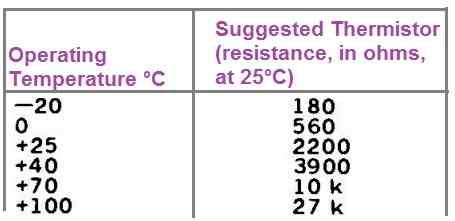
Choose the preferred temperature in column 1.
Column 2 has the thermistor's matching nominal value. At the normal working temperature, the resistance of the thermistor will range from 1 to 4 k.
Since there will be just a small amount of hysteresis, or deadband, between the on and off switching thresholds, the circuit can be utilized to operate a heater, etc., for controlling temperatures in non-critical scenarios.
Reduce the magnitude of resistor R4 to increase the deadband if required.
How the Circuit Works
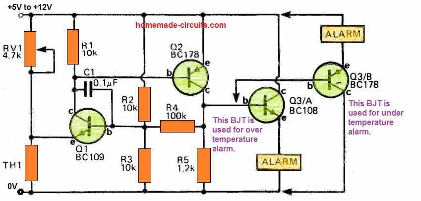
A voltage divider constructed out of the junction of RV1 and TH1 (a thermistor) is linked to the emitter of transistor Q1. The voltage at Q1's emitter is going to change with temperature exactly as the thermistor TH1 does.
A nice little Schmitt trigger is created using the transistors Q1 and Q2. Actually, the Schmitt trigger is nothing but a simple positive feedback amplifier.
Transistors Q1 and Q2 are going to be shut off, or not conducting, if the temperature falls below the threshold as defined by the preset trimpot RV1.
R2, R3, R4, and R5 together determine the voltage at the base of Q1. Given that Q2 is inactive, the parallel configuration of R4, and R4 with R3 is unaffected.
As a result, the base will have 2.86 volts using a 6 volt supply. Q1 will switch on if its emitter voltage goes below 2.86 - 0.6 volts, or 2.26 volts.
This activates Q2, thereby placing R4 in parallel with R2 and causing Q2 to be switched on. This makes Q1 latch on, therefore the transistor must now be turned off by its emitter voltage exceeding 3.14 minus 0.6 volt.
The variation across these two voltages is going to be higher when R4's value is decreased, elevating the deadband.
Q3 drives the relay or alarm while Q2's output is buffered by Q3.
By employing the proper Q3 configuration, this temperature alarm circuit could be utilized in the form of an over-temperature alarm, under-temperature alarm, or both.
2) Highly Accurate Temperature Alarm using Op Amps
This second temperature alarm circuit I have explained below generates an alarm sound whenever temperature detected by the sensor exceeds a set threshold.
The alarm's reliability and potential modifications are also discussed below. The temperature alarm utilizes the LM334Z chip for detecting the variations in the surrounding temperature.
Using LM334Z as the Temperature Sensor
The LM334Z is an integrated chip that produces a constant current and changes its output as the temperature varies.
This can be bothersome if you want a steady current, but it's helpful for making thermometers.
How the Circuit Works
With reference to the shown circuit diagram, the working of the temperature alarm circuit can be understood from the following points:

The current from LM334 makes a voltage across R1, which is compared with a set reference voltage from RV1. IC2b acts as an oscillator.
Let's say the positive input has a higher voltage than the negative one. So, the output of the op-amp is high, just a bit below Vcc.
This makes the positive input about 2/3 of Vcc due to R7, R8, and R9. As long as the output is high, the positive input's voltage rises as C1 charges through R10, until it hits around 2/3 of Vcc.
Then, the op-amp's output goes low, causing the positive input to drop to 1/3 of Vcc, and C1 starts to discharge.
When the negative input's voltage falls to 1/3 of Vcc, the output goes high, and the cycle repeats. We've received many Tech Tip suggestions with odd oscillator circuits, so let's explain why this circuit reliably oscillates.
When the negative input of IC2b matches the positive input voltage, the op-amp's output is about to go low. The key point is that C1's voltage keeps rising while the IC's output drops, until it falls below roughly 2/3 of Vcc.
However, any dip in output voltage pulls down the positive input immediately, maintaining the reason for the switching action (negative input being higher) even as the output drops.
By the time the output drops so much that C1 can't charge anymore, the positive input is already well below the negative input.
Any further output drop only increases this difference, keeping the switching going until the output reaches its lowest point. Just to clarify about the LM358, its highest voltage limit is about Vcc-1.5V.
So, while the exact input switching levels aren't exactly 2/3 and 1/3 of Vcc, the principle remains. Now, about the bath minder: when IC2a's output is low (cold temperature), the oscillator runs freely.
D1 and R6 halt it when the temperature, and IC2a's output, is high.
The suggested transducer was used mainly because we had one around, but you're not limited to that type.
We didn't specifically match its frequency or drive requirements, so you can experiment.
For a change, you might increase C1 to around 10µ, take out R11 and LS1, and put a buzzer module between IC2b's output and ground.
This alteration turns the alarm into an on-and-off buzzing sound, which might work better than the recommended transducer if you plan to set up the circuit permanently.
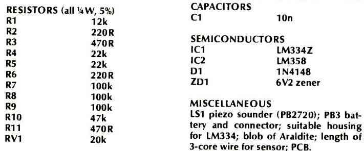
Parts List
The parts list for the above explained temperature alarm circuit can be witnessed in the following image:
Applications
The LM334Z chip, with its temperature-dependent current source characteristics, finds diverse applications.
It's notably useful in constructing thermometers due to its linear response to temperature changes.
Additionally, its output variation with temperature can be harnessed for creating temperature alarms, where oscillations trigger alerts based on temperature fluctuations.
This versatile chip serves as a foundation for building temperature-sensitive systems with precision and adaptability.
Precision Temperature Alarm Circuit using LM335
This third design is a precision temperature monitoring system which incorporates the IC LM335, a National Semiconductors temperature sensor, in conjunction with a window comparator circuit.

This setup facilitates temperature monitoring and utilizes three distinct LEDs (red, yellow, and green) for status indication.
For added functionality, you can attach a relay driver to enable alarms or switching operations. This system proves particularly useful for overseeing the temperature of a heatsink, as seen in applications like audio power amplifiers.
Two trimpots, RV1 and RV2, serve to establish upper and lower temperature thresholds. TD1, the sensor, generates a temperature-dependent reference voltage, changing at a rate of 10 mV per degree Celsius.
By adjusting the set points, you can configure the green LED to illuminate when the sensor registers temperatures below approximately 50 degrees, while the yellow LED activates up to roughly 80 degrees.
Beyond that, only the red LED remains lit. ZD1 functions as a 3.3V zener diode.
If desired, you can incorporate the relay driver into the circuit, as indicated by the dashed lines. It's worth noting that the entire system operates on a 12V power supply.


Comments
Hi Swagatam, I am trying to design a circuit to detect water running that inadvertently was left on. I am thinking that I can use a NTC thermistor taped to the sink drain line. When water is running the pipe will become cooler which will trigger a 555 circuit that will trigger a cd4060 to begin oscillating by grounding pin 12 with a NPN transistor to ground. If the water is shut off prior to the cd4060 reaching pin 3 timing, then the cd4060 resets because it is also connected to positive voltage through a 1k resistor. If the water is not shut off, the cd4060 reaches pin 3 timing and the output from pin 3 triggers an alarm. What do you think? I have merged two circuits that I got from the internet, but I would like for you to view the merged circuit as I am not really sure of the correctness of the sources. If you think this idea is worthwhile, I will email a copy of the circuit for your review. Thanks!
Hi Norman, I don’t think the thermistor will be able to detect and translate the minute difference in temperature between the normal room temperature and the water temperature. So I am quite sure this concept won’t work.
i want to have video of this project . I want to make this project I am facing problem in understanding it
Sorry, video may not be available for this project, but I can definitely help you to understand the circuit stages and complete the project successfully if you want.
I am bsc 2 nd year student . I have to make one pcb designing and fabrication project. Is this project good option or not?
It actually depends on your choice and requirement. I am not sure whether this project is good or not because there can be other better projects in this blog which you could consider. If you give me more hints about your requirements, I can suggest you a better project than the above.
Thank you so much. I want to do innovative project .but I have only four hours in the college to do it in a week . So I want such project that I am also do it myself at home . All the things will be provided by the college like apparatus required so i also want that in case my project require such components that college is not providing it ,i can purchase that easily . I want to make unique and useful project . If you can help me in this , I will be very thankful to you. Thank you ????
Ok, got it. Since you have presently selected a temperature sensor based project I will recommend you to try the last circuit from the following article which is much simpler and easy to build. The relay contacts can be suitably configured with an alarm if you want to make it work like an alarm.
https://www.homemade-circuits.com/lm35-circuit/
Sir , can you give the list of components required in this project the one suggested by you
I will try to update it soon under the same article.
hello sir .
I tried to make temperature sensor but it is not working. can you help regarding it
Hello Tarun, the above circuits are little complex designs which are not suitable for newcomers, you can try the following idea, it is much easier and failproof.
https://www.homemade-circuits.com/wp-content/uploads/2023/11/temperature-alarm-circuit-using-LM35.jpg
The transistor can be a 2N2222
Thank you sir . Sir tell something related to footprint also .I found much problem in setting footprint. Sir , after making circuit how will I come to know whether it is right or not
Hi Tarun,
To adjust the circuit initially keep the 4k7 trimpot wiper fully towards the 10K resistor. Now heat the LM35 to the desired levels, make sure it does not exceed 80 degrees Celsius. Now adjust the 4k7 trimpot until the LED just illuminates and the relay clicks ON. Now remove the heat source, after a couple of seconds the LED/relay should shut OFF….placing the heat on LM35 again should cause the LED to switch ON again.
Thank you