This simple circuit can be used to emulate the operation of a music box. The number of notes may be limited to 10 at the most, and therefore is capable of generating a simple melody.
By: Akanksha Rathode
Circuit Operation
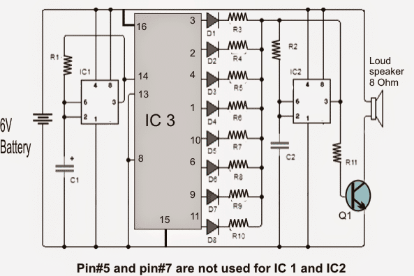
The circuit uses two popular integrated circuits: The timer 555 and 4017 decade counter
Operation of the circuit of music box may be learned as follows:
The left 555 is used as clock generator for the 4017 decade counter.
The operating frequency of the clock can be altered and adjusted simply by changing the value resistor R1 or by replacing it with a potentiometer 50K ensuring a 1K series resistor of 1K so that you don't accidentally move the pot to short the supply with pin7 of the IC.
When the left IC 555 clock rate is varied, the speed of the 4017 output sequence is changed proportionately which determines the musical sounds of the box
The above output signal 555 feeds the clock input of CD4017 which delivers 10 active outputs (high voltage) sequentially beginning with 0 and ending exit at junction 9.
As may be seen in the diagram the outputs 3 and 6 of the 4017 outputs are not used. This is purposely done in order to create spaces of silence in the melody from the music box.
Each CD4017 output may be seen feeding a series diode with a resistor which effectively links the corresponding resistor in series with the second resistor R2 555.
The above arrangement in conjunction with the capacitor C2, force the second 555 to oscillate at a specific predetermined frequency.
Whenever a CD4017 output is activated, the right hand side 555 oscillates at a frequency prefixed by the set R (of the outputs of 4017), in conjunction with R2 and C2. Once the entire sequence of the 4017 outputs are implemented, the IC is reset and process is repeated.
To operate the speaker transistor Q1 has to pass the saturation cutting frequency ranges to which the second 555 is configured at.
As can be seen, the project enables us to experience and achieve a sequenced set of notes as per the liking of the user. Experimenting with the values of the resistors in series with the diodes may be a good idea to start with.
You can also experiment and change the spaces and location of the "silences", by randomly leaving or choosing from the other pins of the 4017 outputs.
The music box circuit is powered with 9 volt PP3 battery or from a 9V AC/DC adapter.
Circuit Diagram
Bill Of Materials for the music box circuit
- IC1 = IC2: 555 timer
- IC3: CD4017 decade counter
- Q1: TIP29 NPN bipolar transistor or the like
- R1 = R2: 33K resistor
- R3 = R5 = R9: 10K resistors
- R4 = R7 = R10: 15K resistors
- R6 = R8: 22K resistors
- R11: 470 ohm resistor
- C1: 10uF/25V
- C2: capacitor of 10nF
- D1 = D2 = D3 = D4 = D5 = D6 = D7 = D8: diode 1N4148 or equivalent
- LS: Miniature speaker 8 ohms.

Comments
And, of course, I just found your discussion of Pin 12 & how to cascade chips for more outputs????:
https://www.homemade-circuits.com/how-to-understand-ic-4017-pin-outs/
Cheers!
~ Jon G
Thank you! Yes that post explains a few cascading methods for 4017. I have another post which also explains how to cascade 4017 for generating 18 LED chaser circuit:
Simple LED Chaser Circuits – Knight Rider, Scanner, Reverse-Forward, Cascaded
Hi Swagatam!
What a great website! Thank you for your website and all of your FUN (and practical) circuits. They remind me of the Forest Mims books I poured through as a child. The 4017 was my favorite chip. I built many circuits with this chip, but I’ve never seen such an array of CLEVER circuits using the 4017! You have a wonderful artistic & intuitive talent!
I read above where you said that this application is linited to 9 notes. I wondered why you didn’t mention the cascading feature of pin 12 where the outputs coukd ve expanded using additional 4017 chips… Just my humble amateur hobbyist $0.03. ????
Also, it might behoove you to add a warning about CMOS & static & perhaps some quick suggestions about handling the chips & grounding. I always use sockets to.make replacement (or scavenging a chip from a disused or abandoned project) easy to do in case I zap a chip!
Thanks again for all of the great circuits… And your thorough explanations which are interesting and highly educational!
Cheers & all my best for a Happy & Healthy 2023!
~ Jon G.
Thank you so much Jon,
I am so glad you liked this website.
IC 4017 is also one of my favorite ICs because it is so versatile and allows us to build so many different projects.
Yes, you can cascade as many 4017 as you want to upgrade any circuit to any desired levels.
I believe the CMOS ICs are not so vulnerable nowadays. Whatever circuits I have built so far using these ICs I have never used socket’s for them, and they always worked fine.
That said, using sockets for any IC is always a good practice.
Many thanks to you for visiting this site, please keep up the good work.
Cheers!
Thanks so much. You are so good at responding quickly.
You are welcome Norman
Hi Swagatam,
I have a circuit with a cd4060 driving a cd4017. I am using pin 3 on both to achieve a time delay. The output from the cd4017 is driving a transistor that grounds the music chip trigger. I bread boarded it and used a 10K resistor and a 1uF ceramic capacitor inline from the cd4017 pin 3 output to the transistor base. I placed 1M resistors to ground from both sides of the capacitor and it worked. I used an AO3400 mosfet on the PCB(I have no idea why) and the chip played continuously. I surmised the mosfet reacts to voltage and not current, so I plan on changing the mosfet to a s8050 transistor. I bread boarded it again and used a s8050 transistor and it works perfectly. I just wonder if this is a proper design? Is this a workable solution? Is it a terrible design? Is there another better way to make the output from the cd4017 be a short pulse so it does not cause the music chip to loop and continuously play. As always, space is limited. Thanks!
Hi Norman, using a series capacitor at transistor base is probably the only way you can switch OFF a transistor after some delay, there’s no other way to do this, so it cannot be a terrible design.
You can get the same effect even with a MOSFET by placing a smaller resistor directly across the gate/source of the MOSFET
The music box (2 x 555 + 4017) of hobbyist Akansha besides its unique design lacks of a missing component in the diagram, that is, if it is not included a diode between common point of R2 and R3 .. R10, and second 555’s pin 3, while discharging C2 does not need it, it is useless to have the contribution from each current I3 ..I10 to the charging of C2 during the scanned t1. If it is fixed, that might be a five-star Jose ring bell idea!
Hey, I am trying to make this circuit work but it only emits a high whining sound and does not seem to cycle through the diodes. I have tried troubleshooting a lot of things but nothing seems to fix it.
Hey, you can try configuring the IC1 with the 4017 in the following manner, and check if that helps