• Skip to main content
  • Skip to primary sidebar

Homemade Circuit Projects

Need circuit help? Post them in the comments! I've answered over 50,000!

Blog | Categories | About | Contact | Calculators-online
You are here: Home / Automobile Electronics / Simple Motorcycle Security Alarm Circuit

Simple Motorcycle Security Alarm Circuit

Last Updated on February 2, 2024 by Swagatam 4 Comments

In this article I have explained a simple motorcycle ant-theft security alarm circuit using a tilt switch and a TTP223 touch switch.

Table of Contents
  • Design Request and Specifications
  • Basic Working Principle
  • Circuit Description
  • Parts List

The circuit was requested by Mr. Sergei, as given below.

Design Request and Specifications

I am a motorcyclist and I would like to ask you to design a simple and cheap alarm system for my motorcycle. For example using a tilt sensor. Maybe with activation/deactivation by touching ttp223 sense pad.

Basic Working Principle

The tilt switch remains activated while it is in the tilted mode or while the motorcycle is parked on its stands and is leaning at an angle. In this mode the owner of the motorcycle powers and arms the circuit through a hidden TTP223 touch switch module.

In this situation if a thief tries to steal the bike by removing it from the stand, the motorcycle is aligned horizontally straight, causing the tilt switch mercury to changeover.

The internal changeover of the tilt switch instantly toggles ON an IC 555 monostable and an attached siren.

The siren sounds alerting the people around, and the owner regarding a possible motorcycle theft.

Circuit Description

The following figure depicts the complete circuit design of the motorcycle anti-theft alarm circuit, using tilt switch and TTP223 module.
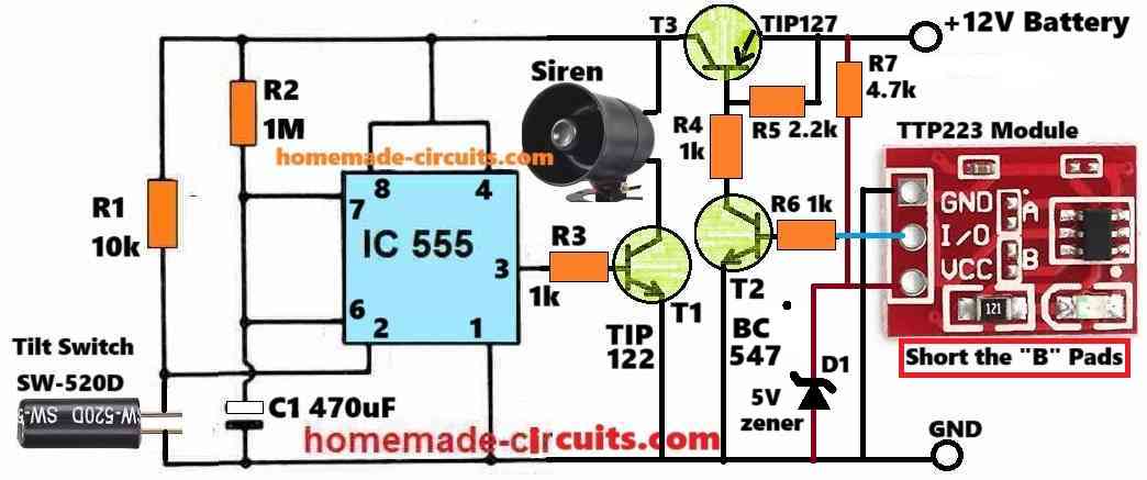
Simple Motorcycle Security Alarm Circuit

The working of the proposed motorcycle anti-theft alarm circuit can be understood with the following points:

The TTP223 is configured as a touch ON/OFF toggle switch.

When the motorcycle is parked and leaning on its stands, the TTP223 is activated by the owner, by touching the touch pad on the reverse side of the module.

Once toggled ON, the OUT pin of the TTP223 module sends a positive voltage to the base of T2 turning it ON.

With T2 turned ON, T3 is also turned ON, and T3 now powers ON the IC 555 circuit.

The IC 555 is configured as a monostable multivibrator. In this configuration, the IC 555 generates a momentary high logic at its pin#3 whenever its pin#2 is grounded.

The time for which this momentary logic high at pin#3 stays active depends on the values of R2 and C1.

This logic high becomes responsible for activating the T1 and the alarm siren.

Now, as stated above, pin#3 of the IC 555 goes momentarily only when its pin#2 is grounded.

As shown in the diagram, a mercury tilt switch SW-520D is connected between pin#2 and ground.

While the motorcycle is parked on its stands and inclined at an angle, the mercury inside the tilt switch rolls down at one end of the tube.

This keeps the contacts of the tilt switch disconnected internally, so that pin#2 of IC555 stays disconnected from the ground.

Now suppose, an unfortunate thief attempts to steal the motor bike and in the process pulls the bike vertically straight.

As soon as this happens, the mercury inside the tilt switch flows across the other end and shorts its internal contacts.

This instantly grounds the pin#2 of the IC 555 causing its pin#3 to go high, switching ON T1 and the alarm.

The burglar may try a desperate attempt to restore the motorcycle back to its original position, but that won't help to stop the alarm.

Depending on the values of R2 and C1, the alarm remains activated for some time and then it stops automatically.

By the time the alarm stops, the owner is already alerted regarding the situation so that he can quickly respond to the situation.

Parts List

  • Resistors are 1/4 watt CFR 5%
  • 1k = 3
  • 10k, 1M, 2.2k, 4.7k = 1 each
  • Semiconductors
  • Transistors TIP122, TIP127, BC547 = 1 each
  • IC 555 = 1
  • TTP223 module = 1
  • Tilt switch SW-520D = 1
  • zener diode 5V 1/2 watt = 1

You'll also like:

  • 1.  Automotive LED Driver Circuits – Design Analysis
  • 2.  Build a Homemade GSM Car Security System
  • 3.  Footsteps Detector Circuit
  • 4.  2-Pin Motorcycle Turn Signal Flasher Indicator Circuit with Buzzer
  • 5.  Make this Simple Refrigerator Door Open Alarm Circuit
  • 6.  LED Lamp Circuit for Motorbike Headlamp

About Swagatam

I am an electronics engineer with over 15 years of hands-on experience. I am passionate about inventing, designing electronic circuits and PCBs, and helping hobbyists bring their projects to life. That is why I founded homemade-circuits.com, a website where I share innovative circuit ideas and tutorials. Have a circuit related question? Leave a comment.... I guarantee a reply!

Previous Post: « Day/Night Triggered Automatic Door Lock Circuit
Next Post: Car Battery Warmer Circuit »

Reader Interactions

Comments

  1. Sergei Boldyrev says

    February 1, 2024 at 6:09 pm

    1. I will assume that 2 – 5.5 V DC is needed to power the TP223 module. However, this is not a problem, it is easy to add an LM7805 Linear Regulator LM7805 or similar to the power supply circuit.
    2. Does the siren sound continuously or intermittently?
    3. Where in the circuit can I add a ‘breathing LED’ circuit on ne555 as an arming indicator?

    Reply
    • Swagatam says

      February 1, 2024 at 7:35 pm

      OK, here are the answers:
      1.Yes 5v can be used through a 7805 ic for the ttp223, or through a zener/resistor network.
      2.The siren sound will continuous but if an intermittent type siren is used the sound will be intermittent. However the siren will be on only for sometime depending on the values of R2 and C2.
      3.You can connect a 555 based breathing circuit directly across the supply terminals of the existing alarm circuit.

      Reply
  2. Sergei Boldyrev says

    February 1, 2024 at 4:31 pm

    Dear Swagatam! Thank you for the solution and for the article!

    Reply
    • Swagatam says

      February 1, 2024 at 5:19 pm

      Thank you Dear Sergei! Its my pleasure!

      Reply

Need Help? Please Leave a Comment! We value your input—Kindly keep it relevant to the above topic! Cancel reply

Your email address will not be published. Required fields are marked *

Primary Sidebar

Subscribe to New Circuit Ideas

Categories

  • Arduino Projects (87)
  • Audio and Amplifier Projects (132)
  • Automation Projects (17)
  • Automobile Electronics (101)
  • Battery Charger Circuits (83)
  • Datasheets and Components (104)
  • Electronics Theory (143)
  • Free Energy (37)
  • Games and Sports Projects (11)
  • Grid and 3-Phase (19)
  • Health related Projects (25)
  • Home Electrical Circuits (12)
  • Indicator Circuits (14)
  • Inverter Circuits (87)
  • Lamps and Lights (142)
  • Meters and Testers (69)
  • Mini Projects (46)
  • Motor Controller (64)
  • Oscillator Circuits (27)
  • Pets and Pests (15)
  • Power Supply Circuits (108)
  • Remote Control Circuits (50)
  • Security and Alarm (64)
  • Sensors and Detectors (101)
  • Solar Controller Circuits (59)
  • Temperature Controllers (42)
  • Timer and Delay Relay (49)
  • Transmitter Circuits (29)
  • Voltage Control and Protection (37)
  • Water Controller (36)

Calculators

  • Battery Back up Time Calculator
  • Capacitance Reactance Calculator
  • IC 555 Astable Calculator
  • IC 555 Monostable Calculator
  • Inductance Calculator
  • LC Resonance Calculator
  • LM317, LM338, LM396 Calculator
  • Ohm’s Law Calculator
  • Phase Angle Phase Shift Calculator
  • Power Factor (PF) Calculator
  • Reactance Calculator
  • Transistor Astable Calculator
  • Transistor base Resistor Calculator
  • Voltage Divider Calculator
  • Wire Current Calculator
  • Zener Diode Calculator
  • Filter Capacitor Calculator
  • Buck Converter Calculator
  • Boost Converter Calculator
  • Solar Panel, Inverter, Battery Calculator
  • Wire Current Calculator
  • SMPS Transformer Calculator
  • IC SG3525, SG3524 Calculator
  • Inverter LC Filter Calculator

People Also Search

555 Circuits | 741 Circuits | LM324 Circuits | LM338 Circuits | 4017 Circuits | Ultrasonic Projects | SMPS Projects | Christmas Projects | MOSFETs | Radio Circuits | Laser Circuits | PIR Projects |

Recent Comments

  • Swagatam on Battery Deep Discharge Protection Circuit
  • Swagatam on 10 LED Tachometer Circuit Diagram
  • Drew Adare on How to Collect Free Energy from Atmosphere
  • Göran on 10 LED Tachometer Circuit Diagram
  • Abdulmajid Haruna on Laptop Power Bank Circuit

Company

  • Privacy Policy
  • Cookie Policy
  • About Me
  • Contact
  • Disclaimer
  • Copyright
  • Videos
  • Sitemap

Social Profiles

  • Twitter
  • YouTube
  • Instagram
  • Pinterest
  • My Facebook-Page
  • Quora
  • Stack Exchange
  • Linkedin
  • © 2025 · Swagatam Innovations