In this post I have explained a delay OFF adjustable motor controller circuit so that the motor can be assigned a fixed predetermined operating time, or delay OFF time. The idea was requested by Mr. Cribey
Technical Specifications
I really like your website. It is very helpful for so many people.
I am trying to control a 36RPM geared 9V motor speed and time that it is on in the reverse direction only (counter-clockwise).
In effect I would like to use a 5V USB adaptor plug (like the ones we use for our phones) to power the motor on for a chosen speed and for a chosen amount of time.
BOTH the speed and time need to be adjustable (potentiometers maybe?) to get the exact right time for the motor to be on for, and at the correctly chosen speed.
Any help would be really appreciated.
Regards,
Cribey
The Design
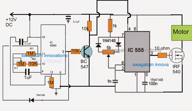
The proposed motor speed controller circuit presented here features an adjustable PWM speed control and an adjustable delay control for the associated motor, which needs to be controlled.
As may be seen in the above diagram, the circuit incorporates two discrete stages, one consisting of the versatile IC 4060 and the other using the work horse IC 555.
Basically both these are timer ICs by nature, however here the IC 555 is configured as a PWM controller whose PWM output is adjustable using the associated 5K pot.
Therefore this stage takes care of the motor speed control and may be set to any desired speed by manually adjusting the 5K pot.
Now as requested, the motor needs to be switched ON only for a particular duration of time, and this is implemented by the 4060 C stage. The delay time which needs to be fixed for enabling the motor to be switched OFF once this elapses is adjusted by the 1M pot associated with pin#10 of the IC 4060 and indicated as P1, the 1uF capacitor also becomes directly responsible for determining the time delay for which the motor may remain switched ON.
When power is switched ON, the IC switches ON the motor and allows it to operate at a particular speed as specified by the adjustment of the 5K pot.
Also simultaneously the IC 4060 begins counting, and as soon as the specified time span elapses, pun#3 of this IC goes high triggering the NPN BC547 transistor into conduction.
The transistor grounds the pin#4 of the IC555 thereby completely disabling the IC 555 and the mosfet at its pin#3, such that the connected motor instantly comes to a halt.
The diode connected across pin#3 and pin#11 of the IC 4060 makes sure that the above condition stays latched until the power is switched OFF and ON again for initiating a fresh cycle.
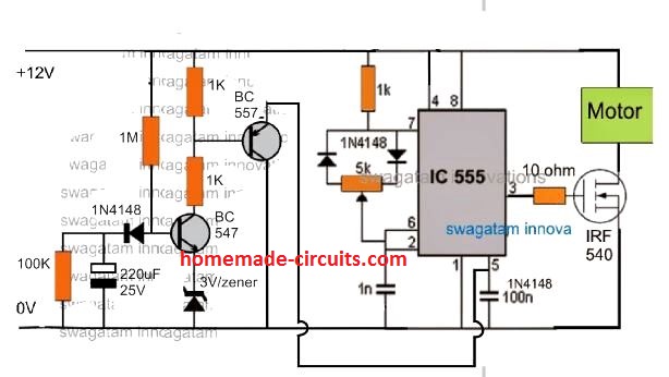
Another simpler version of the above circuit is shown below. It uses a transistorized delay OFF circuit instead of the IC 4060.


Comments
Hi Swagatam, can I use this circuit to run a 24 volt, 10 amp, (250 watt) DC brushed motor on a small ebike? I could probably rig up a thumb throttle to the pot so it’s beside the handle. If not, would you have a simple circuit for an ebike like this? Thanks.
Hi Gabriel, yes definitely you can use the circuit for the mentioned purpose.
I have another similar circuit, although slightly more complex, which can be also tried.
Simple E-Bike Circuit [Electric Bike]
Hello,
On the schematic that you sent me on the right bottom corner above the capacitor terminal 5 100n, what does 1N4148 represent? Why is this added above the 100n?
Thank you
sorry, it is a mistake, please ignore the 1N4148 print
Hello,
Thank you so much for your prompt reply and for the diagram. A couple more follow-up questions, please.
1) Based on this schematic, will it provide the most power/torque outputfor our DC motor nominal 9V 2400rpm?
2) How do you calculate the components if we want to delay OFF circuit (for example from 5 min to 10 min)?
Thanks again,
Boris
Sorry to inject myself here! I need a circuit that delays the max torque to a motor on an esc which is different than the one in this thread. I can’t find where I can post a new request as I can’t find the main comment box!
Thanks Pete
The torque will depend on the adjustment of the PWM 5K pot. he range will be from 5% to 95%.
The delay ca be adjusted by adjusting the values of the 1M resistor and the 220uF capacitor
Also would be even better if LED would start blinking after 5 min without stop the motor.
Thanks, Boris
Hello,
How could I modify the most simple way this circuit to run with a permanent set time (let stay 5 min. until turned off)?
Thanks.
Hi, I have updated the design at the bottom of the post
Dear Sir, Need circuit for 3.7 rpm dc motor run with left and right direction in every 2 hours (For incubator)
Dear Vino, you can use any IC4060 based timer circuit for achieving this, by connecting a relay transistor driver with pin#3 of the IC.
you can try the following
https://www.homemade-circuits.com/2015/01/reverse-forward-motor-timer-circuit-for.html
Actually at pin 3 I am not reading any voltage but I know voltage is passing but it activated the gate of the logic Fet but not the regular Fet and if the supply voltage is 10v to pin 8 and 4 then output from pin 3 would be less…. Wouldn't it be 5v or less from pin 3?
pin#3 will give you a peak voltage that's almost equal to the supply voltage, if you are not getting anything at pin#3 then your IC could be faulty, you can recheck it by removing the fet from pin#3 of the IC
I was using a logic get when I was getting 5v output, I changed to irfz44n and I got no output which is telling me that the gate voltage isn't high enough and remember i was only getting 10v supply to the 555.
I changed one of the 1k resistors to 1.5k and I got 11v to the 555 I was trying to get 12 to 15v
gate of mosfet is also a logic gate…
10V is quite enough to trigger any standard mosfet, and please remember since pin#3 would be in the form of a frequency your DC voltmeter would indicate much less voltage than the actual peak value depending upon the duty cycle.
if the duty cycle was 50% then your meter would show 50% of the supply at pin#8/4
now this actually means that pin#3 should indicate less than 6V….if the supply at pin4/8 is 12V
Ok I will work on one, in the mean time I built this circuit today
https://drive.google.com/file/d/0B0N-CQJdWSP0NHFzbTdTR3FmTVk/view?usp=sharing
I used the 10ohm at the gate of the fet but I was only reading 5.2v Dc output.
pin 1 and 8 of the 555 I was only getting 10V I couldnt read an output at pin 3. One of the 1k resistors in the voltage divider was hot also, not sure why I am not getting 12v to the ic but Ill assume that thats the reason why I am not getting full volts at the output because It might not be switching the Fet fully on.
…you can try increasing the 1K to 2k2 and see if that helps to keep the resistor cooler
the results which you are getting are all incorrect and could happen only if the IC is faulty.
IC 555 along with the mosfet cannot consume more than 5 to 10mA and therefore no voltage can drop or no resistor can become hot anywhere in the circuit.
this is what I came up with.
https://drive.google.com/file/d/0B0N-CQJdWSP0TlFvbk5lM040cEk/view?usp=sharing
that's a voltage doubler not a boost converter, boost converter will require an inductor or a flyback transformer.
Where I am now I dont have much transformers available, I only have 24v can I build a voltage doubler circuit to further increase the voltage going to the motor to get some more speed.
the transformer is 10amps and the motor is drawing 2.3amps its rated 0-90v.
voltage doubler circuit will not work, you must upgrade the above design to a boost converter instead
ok like this
https://drive.google.com/file/d/0B0N-CQJdWSP0NHFzbTdTR3FmTVk/view?usp=sharing
now it's better, except the mosfet gate 10K, which should be 10 ohms…
how does this look?
https://drive.google.com/file/d/0B0N-CQJdWSP0NHFzbTdTR3FmTVk/view?usp=sharing
oK got it, it's for dropping the 24V to 12V….in that case you can use two 1K resistors, 100 ohms will simply become hot and burn,
and R2 end should be also connected with pin8/4 and not with 24V
It is OK, but what's the two 100 ohms for at pin4/8 of the IC?
it's not required you should connect the pin8/4 directly with positive.
and R1 should 10 ohms not 10K
Ok and the current that the circuit would be able to manage would just depends on the FET's drain source current?
In this case it could manage a motor up to about 20-28amps
yes that's correct!
How could I modify this circuit to run without a set time (stay on until turned off)?
remove IC 4060 stage and connect pin4 of IC 555 with positive.
Hi, You can try the concept presented in the following article, if you have problems let me know, I'll try to help!!
https://www.homemade-circuits.com/2015/06/pwm-motor-soft-start-circuit.html
I read it on a website when trying to understand the 555 a little bit more.
Anyway I know it can be configured to below 50% DC but my fear was drift in frequency.
anyway I will construct the circuit and test.
if you want to achieve a perfectly isolated PWM, and frequency control, you can try the following design, the first one:
https://www.homemade-circuits.com/2011/12/how-to-build-pure-sine-wave-inverter.html
Hello Sir
the 555 pwm section.
Is the PWM adjustment independent of frequency? as I know 555 have issues going below 50% duty cycle.
I am aimimg to get at about 10% duty cycle at about 50hz. Want to to try out some stuffs.
Also can one get a frequency as low as 50hz or even 20hz from the 555 section
Hello Michael, where did you learn this…as far as I know, you can achieve right from 5% to 95% duty cycle control using the circuit that's shown above.