In the following post I have explained a simple yet useful car speed limit warning indicator circuit which can be used in vehicles for getting an instant indication of a possible over speed limit conditions. The idea was requested by Mr. Abu-Hafss.
Technical Specifications:
Shall appreciate, if you could design a circuit to warn with some melody that the car has reached preset speed limit. As soon as the speed is reduced below the limit the alarm should go off.
The circuit should have 2 options for switching between 2 speed limits.
1. The circuit should have a selection switch --- Postion A >> 100Km/h (for ordinary highways) and Position B >> 120 Km/h (for Experessways).
2. When the switch is positioned for example at position B, a sensor which can get current speed from car speed-o-meter and then compare with the selected speed limit (120 Km/h). Whenever, the sensor reads the speed to be 120 Km/h or more, it will start playing a warning melody until the speed is reduced.
The Design
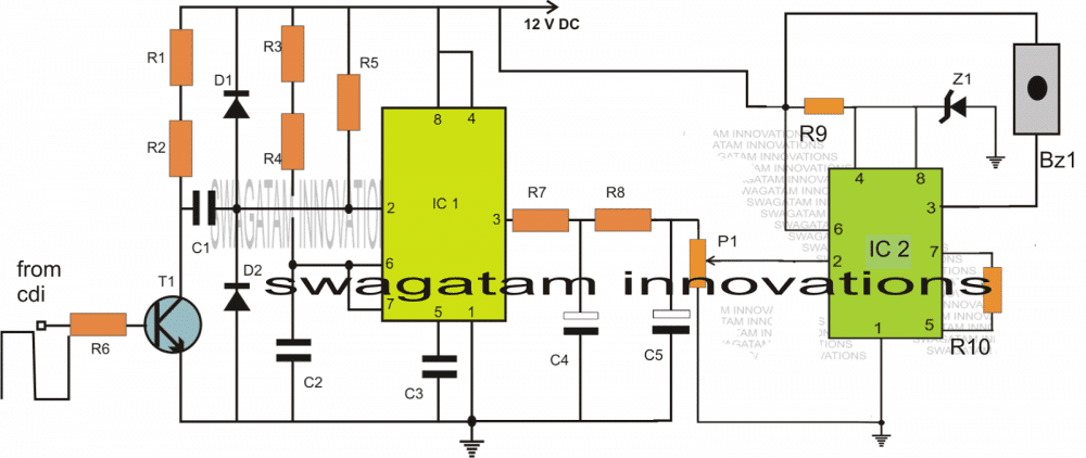
The designed circuit of a car over speed limit indicator basically consists of two stages. Both the stages incorporate the ubiquitous IC 555.
The stage which includes IC1 is configured as a simple frequency to voltage converter or a frequency dependent voltage generator circuit.
Here IC1 is rigged in the form of a standard monostable multivibrator whose ON time is decided by the resistors R3/R4 and the capacitor C2. These components must be selected appropriately for getting most favorable output response.
As we all know that all modern motor vehicles today incorporate electronic ignition systems which invariably include a CDI or a capacitive discharge ignition network, in contrast to the older circuit-breaker units.
The the CDI unit is responsible for generating the required igniting sparks inside the engine of the vehicle and its rate of firing is directly proportionate to the speed of the vehicle.
It means with an increase in the speed of the vehicle the charge/discharge rate of the CDI capacitor also increases and vice versa.
The monostable built around IC1 exploits this feature of the CDI system and derives a sample potential from the CDI at the base of T1.
T1 effectively switches the varying high voltage pulses from the CDI into low voltage triggering pulses across C1 and ground.
With response to the above pulses, every time T1 conducts it pulls pin#2 of IC1 to ground initiating the monostable output to go high.
The monostable sustains the output in the high position for a period determined by the values of the respective timing components as explained in the previous section.
However, the continuous train of pulses initiates an appropriately stabilized high output at pin#3 of IC1 (due to the functioning of the monostable which produces almost an exact average DC output proportional to the frequency of the pulses.)
Circuit Operation
The output is further stabilized into a perfect measurable equivalent DC by the integrator stage comprising R7/R8/C4/C5 and also P1.
IC2 is wired up as a voltage comparator.
Its pin#2 is allowed to receive the varying voltage from the IC1 output.
P1 is set such that as soon as the output from IC1 rises to a certain limit which may be calculated as the over speed limit value, the potential; at pin#3 rises over 1/3rd Vcc
This instantly prompts the output of IC2 to go low, activating the connected alarm device.
This alarm would stay activated as long as the car speed does not come down below the preset limit.
As soon as the speed is reduced, the alarm stops sounding.
The preset P1 may be suitably replaced with a properly calculated potential divider ladder type network along with a selector switch for enabling the selection of different speed limits for different free-ways.
Circuit Diagram
Parts List for the proposed Car Speed Limit Warning Indicator Circuit
- R1 = 4K7
- R2 = 47E
- R3 = CAN BE A VARIABLE 100K RESISTOR
- R4 = 3K3,
- R5 = 10K,
- R6 = 330K
R9 = 1K, - R7 = 1K,
- R8 = 10K,
- R10 = 100K,
- C1 = 47n,
- C2 = 100n,
- C3 = 100n,
- C4 = 100uF/25V,
- C5 = 10uF/25
- VP1 = 10k PRESET
- Z1 = 6V ZENER
- T1 = BC547
- IC1, IC2 = 555,
- D1,D2 = 1N4148
- BZ1 = BUZZER OR MUSICAL ALARM DEVICE
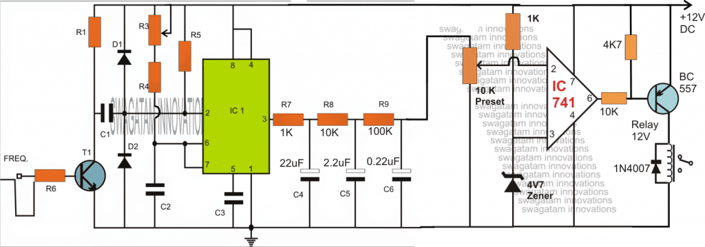
Improving the Design By using an Opamp
The accuracy and reliability of the above explained car speed warning indicator can be further improved by replacing the 555 buzzer stage with an opamp/relay stage as shown below:
Circuit Diagram
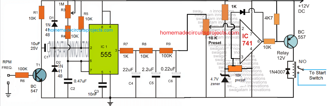
To make the relay latched on detection of an over-speed situation, a hysteresis feedback can be to the above design, as shown below:
Speed Limit Indicator using IC 4011
Pulses from the pickup coil are rectified and clipped at 4V7 after passing through a current limiting resistor. A DC voltage equivalent to engine rpm is delivered to RV1 through Q1 and the diode pump; the sharp transfer characteristic of a CMOS gate is exploited to trigger the oscillator produced by the remaining half of the IC 4011.
A shrill sound which cannot be ignored comes through the speaker at the predetermined 'speed' (revs) threshold, and the sounds fades the moment the speed reduces by three or four mph.
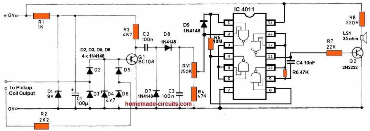
Input pulse can be calibrated with a reliable pulse generator, noting that frequency = revs per minute multiplied by the number of cylinders divided by 120 for a four stroke engine. For a car having a configuration of 17 and 1/2 MPH per 1000 revs, in top gear, f =133Hz at 70 MPH, 124Hz at 65 MPH; for a car with a specification of 17 and 1/2 MPH per 1000 revs, in highest gear, f =133Hz at 70 MPH, 124 (4000 RPM and 3714 RPM).
Q1 must be supplied the required frequency, and VR1 must be adjusted to turn off the siren. On the prototypes, successful switching happens with a fluctuation of just 5Hz (1 50 RPM), maybe less than 3 MPH in the previous case.
Immediate 'on-the-road' measurement, while covering discrepancies due to wheel diameter, etc., will only be as accurate as the speedometer, and thus should clearly be done by a passenger instead of the driver.


Questions & Answers
Hi Swagatam. Thank you very much for what you do. You are helping the world better. You are and wil be blessed more for sure 🙂 . I have a question. What if the car is run on neutral (since my vehicle is Manual honda jazz/fit 2004), isnt it that the CDI coil wil not fire depending on the speed of the vehicle. It wil go back to the normal rpm of 800? And also how wil I connect the circuit if I want to tap it from the Vehicle speed sensor? Do I need some buffer or pre stage circuit or can I just connect directly from the speed sensor (3terminal sensor)? Thank you once again! You are awesome really!
Thank you so much Kitt, I appreciate your kind words!
You are right, in that case the CDI input must be actually configured with the pickup coil output of the vehicle.
If you want to configure the CDI input with your speed sensor, you can do it without a buffer. The R6 an T1 both act as buffers, so no need of any additional buffer stage.
Nice!
I want to applied this circuit to activate ‘auto door lock’ if the car run over 20kpj for example.
But my engine was diesel.
Can I pick the signal from speed sensor rather than coil pulse? What should I change to the circuit?
Also can I calibrate the activation relay?
Thanks.
You can pick the signal from the speed sensor. You can try the second last design and adjust the 10 k preset to the calibrate the relay operation.
Thank you.
If I dont pick up signal from speed sensor ( I’m affraid this can inference the car circuit), yet I install a hall effect sensor, will it work well? Or should I add another component or circuit?
You will have to measure the signal voltage. Any pulse above 5V DC will work, no matter from where it is coming.
Thank you very much. Brother
Brother, I would like to see the last improved circuit that using an Opamp/Relay state.
Thank.
Hi Rambo, I have updated the design for you, you can check it now….
Can you share the matlab simulation of this circuit?
Nice circuit sir, please I wish to ask, where is CDI located inside the car?I can assemble the circuit but don’t know where to locate the CDI thanks n waiting ur help
Thanks for the reply, i will try to contact any local mechanics, i though i just have to built the circuit as given in the diagram, test it and then install it, anything next should be the speed settings
OK great, wish you all the best
Thanks Nkwenti,
you can consult any auto mechanic in your area he will be able to tell where exactly the CDI may be located in your car.
But please build the circuit only after you have understood the stages and functioning perfectly, and first try it on your work bench bfore the final installation
Sir, can you give me some example project about this project? I need some help to solve my circuit.
the diagram is already suggested in the above article.
Hello sir , how to calculated between rpm against km/h?
Hello zas, it will depend on how many RPM covers 1km…then you can divide the total RPM with this value for getting km/h
i think i have responded to your last posting however i am not sure. anyway just in case i didn't, i want to appreciate you and your efforts. and to let you know i am still studying the amendment you make using opamp. i will get back to you as soon as i understand how the combination of the opamp and the transistor will acrually operate. how ever why do you chose to use a PNP transitor instade of an NPN considering Vcc is a positive supply?
thanks abdul, you can use an NPN at the the output instead of PNP, depends how the input of the opamp are configured.
for NPN just swap the inputs of the opamp with each other, meaning now pin3 gets connected with the preset and pin2 with zener reference.
on the output side, the 4k7 gets connected with ground, and the NPN needs to be configured in the usual manner with relay across its collector and positive.
I can't thank you enough. Apka lakh lakh shukriya. i will sturdy it to see how far i can understand how the cct work. i will get back to you. As you know opamps are trick fellows expecially if you connect them in this formation.
you are most welcome Abdul
Thanks a million Mr Swagatam, i understand how to set the speed. As i eagerly await the update of the cct using the Opamp, i will have to do some revision of the Opamp device so that i will be able to flow with you in your explanation. It is great to know that someone out there is willing to give you a helping hand. People like you are rear nowadays.
It's my pleasure Abdul, thanks very much.
I have updated the new diagram at the end of the post, please check it out
Dear, can u make a alarm circuit for vehicle when the police in the street has erected the high speed detecting gun (I think its is IR beam) against the vehicle?
Abdul, you will need to set the circuit by experimenting it practically, meaning you will need to practically cause the engine to attain a speed proportionate to 120km/hour limit and then at this point carefully adjust the preset such that the buzzer start buzzing, however I think the 555 is not an appropriate device for sensing the threshold, an opamp would work better.
I'll try to upadte the new diagram soon.
Thank you Swagatam for the prompt response. P1 appears to be a potentiometer. Now in your beautiful write up above you say, "P1 is set such that as soon as the output from IC1 rises to a certain limit which may be calculated as the over speed limit value, the potential; at pin#3 rises over 1/3rd Vcc" how is the calculation done to achieve a speed of say 120km/hr. i plan to installed the device in the car of my father. thank again.
Thank you Abdul, the D1/D2 are optional and are included to control negative spikes or transients that might possibly enter the circuit causing disturbances in the reading.
The P1 is used to set the threshold speed or the input frequency where the buzzer needs to to sound
Swagatam Majumdar, thank you very much for your efforts. how ever, i will appreciate very much if you can shade more light on 1. the function of Diode D1 and Diode D2. and also can you shade more light on the function of P1. thanks you.
Dear Jayanth, I am not sure what kind of IR these equipment use, but if the signals are detectable using an ordinary IR sensor, then it can implemented by using an ordinary design such as the one discussed in this article.
https://www.homemade-circuits.com/2012/02/how-to-make-simple-infra-red-remote.html