• Skip to main content
  • Skip to primary sidebar

Homemade Circuit Projects

Need circuit help? Post them in the comments! I've answered over 50,000!

Blog | Categories | About | Contact | Calculators-online
You are here: Home / Meters and Testers / How to Measure Gain (β) of a BJT

How to Measure Gain (β) of a BJT

Last Updated on January 8, 2024 by Swagatam Leave a Comment

In this post we'll study a simple opamp circuit design which can be applied for measuring the beta or the forward current gain of a particular BJT in question.

Table of Contents
  • What is beta (β)
  • Operational Details
  • Circuit Diagram

What is beta (β)

The beta (β) is the forward current gain that every BJT inherently possesses. It determines the efficiency of the particular device in terms of its ability to amplify current.

These values can be fundamentally found in the datasheets of the particular device through minimum or approximate of the actual (practical) values.

This implies that one may not know the real forward gain value of a BJT until its tested practically in a given circuit. This may be a tedious looking unless we are able to do it with a simple circuit as I have explained below:

Note that two transistors with the same name (eg BC547) may have different betas. The following circuit can obtain the value of a specific transistor beta.

Operational Details

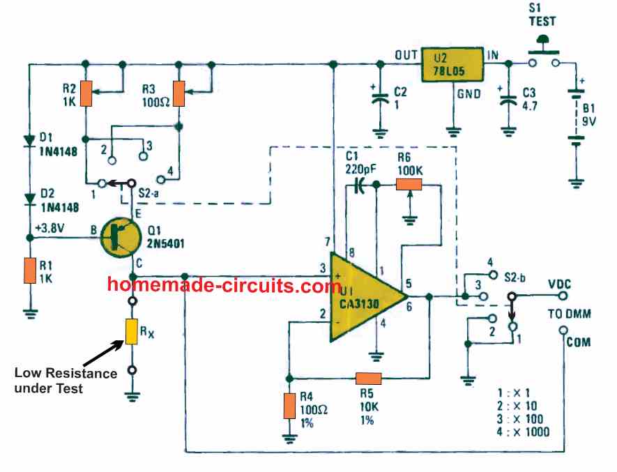
Referring to the circuit diagram, we can see that it consists of a voltage to current converter on the left side of the transistor while a current to voltage converter on the right side. The voltage to current converter to the left becomes responsible of controlling the emitter current of the transistor just as a current to voltage converter may control the base current of a transistor (BJT).

The latter converter design is implemented easily by using an inverting opamp without including an input resistor.

It can be simulated that when powered the base current flows through the virtual ground (point X), the potential (voltage) is not affected by the current as long as the output VB is proportional to this current (Ib) input of the operational amplifier.

Now the circuitry that controls the emitter current is a current to voltage converter circuit that provides the current to the emitter of the transistor.

The base of transistor to held at zero (0) volts (when virtual ground feeds the inverting and non-inverting terminals of the operational amplifier) such that the voltage on the emitter is maintained at -Vbe.

This ensures that the emitter current is established with an input current to the voltage converter and the resulting base current is obtained by measuring the output voltage of the current-voltage converter.

That is,

= 1 + Ie / Ib. As Ie = VA / R1 and Ib = VBR2
= 1 + VA / R1 x R2 / VB = 1 + [VA x R2] / [VB x R1]

With R1 = R4 = 1k, R2 = R3 = R5 = 100K, = 1 + [VA x 100K] / [VB x 1K].

Substituting V+ = VA, beta (β) of the transistor is obtained from the formula:

β = 1 + 100 V+ / VB

Circuit Diagram

MEASUREBETAOFTRANSISTOR 1

You'll also like:

  • 1.  Simple Transformer Winding Tester Circuit
  • 2.  4 Useful Logic Probe Circuits Explored
  • 3.  Simple 1.5 V Inductance Meter Circuit
  • 4.  Arduino based DC Voltmeter Circuit – Construction Details and Testing
  • 5.  How to Make a Shunt Resistor
  • 6.  Light Meter Circuit with LED Bar Graph

About Swagatam

I am an electronics engineer with over 15 years of hands-on experience. I am passionate about inventing, designing electronic circuits and PCBs, and helping hobbyists bring their projects to life. That is why I founded homemade-circuits.com, a website where I share innovative circuit ideas and tutorials. Have a circuit related question? Leave a comment.... I guarantee a reply!

Previous Post: « Make this Simple Music Box Circuit
Next Post: Infrared Remote Control Safe Lock Circuit »

Reader Interactions

Need Help? Please Leave a Comment! We value your input—Kindly keep it relevant to the above topic! Cancel reply

Your email address will not be published. Required fields are marked *

Primary Sidebar

Subscribe to New Circuit Ideas

Categories

  • Arduino Projects (87)
  • Audio and Amplifier Projects (132)
  • Automation Projects (17)
  • Automobile Electronics (101)
  • Battery Charger Circuits (83)
  • Datasheets and Components (104)
  • Electronics Theory (143)
  • Free Energy (37)
  • Games and Sports Projects (11)
  • Grid and 3-Phase (19)
  • Health related Projects (25)
  • Home Electrical Circuits (12)
  • Indicator Circuits (14)
  • Inverter Circuits (87)
  • Lamps and Lights (142)
  • Meters and Testers (69)
  • Mini Projects (46)
  • Motor Controller (64)
  • Oscillator Circuits (27)
  • Pets and Pests (15)
  • Power Supply Circuits (108)
  • Remote Control Circuits (50)
  • Security and Alarm (64)
  • Sensors and Detectors (101)
  • Solar Controller Circuits (59)
  • Temperature Controllers (42)
  • Timer and Delay Relay (49)
  • Transmitter Circuits (29)
  • Voltage Control and Protection (37)
  • Water Controller (36)

Calculators

  • Battery Back up Time Calculator
  • Capacitance Reactance Calculator
  • IC 555 Astable Calculator
  • IC 555 Monostable Calculator
  • Inductance Calculator
  • LC Resonance Calculator
  • LM317, LM338, LM396 Calculator
  • Ohm’s Law Calculator
  • Phase Angle Phase Shift Calculator
  • Power Factor (PF) Calculator
  • Reactance Calculator
  • Transistor Astable Calculator
  • Transistor base Resistor Calculator
  • Voltage Divider Calculator
  • Wire Current Calculator
  • Zener Diode Calculator
  • Filter Capacitor Calculator
  • Buck Converter Calculator
  • Boost Converter Calculator
  • Solar Panel, Inverter, Battery Calculator
  • Wire Current Calculator
  • SMPS Transformer Calculator
  • IC SG3525, SG3524 Calculator
  • Inverter LC Filter Calculator

People Also Search

555 Circuits | 741 Circuits | LM324 Circuits | LM338 Circuits | 4017 Circuits | Ultrasonic Projects | SMPS Projects | Christmas Projects | MOSFETs | Radio Circuits | Laser Circuits | PIR Projects |

Recent Comments

  • Swagatam on 2 Compact 12V 2 Amp SMPS Circuit for LED Driver
  • Alan Bishop on AC Motor Speed Controller Circuits using Back EMF
  • Swagatam on Real MPPT Solar Charger Circuit Using Arduino, LCD, and Manual/Auto Switch
  • Swagatam on AC Motor Speed Controller Circuits using Back EMF
  • Swagatam on DC to DC Converter Circuits using SG3524 [Buck, Boost Designs]

Company

  • Privacy Policy
  • Cookie Policy
  • About Me
  • Contact
  • Disclaimer
  • Copyright
  • Videos
  • Sitemap

Social Profiles

  • Twitter
  • YouTube
  • Instagram
  • Pinterest
  • My Facebook-Page
  • Quora
  • Stack Exchange
  • Linkedin
  • © 2025 · Swagatam Innovations