To make a furnace temperature meter, the sensing element is required to be particularly robust so that it is able to withstand the extreme high temperatures generally developed in furnaces and ovens.
What is a Furnace
The circuit of a pyrometer explained here is based on a thermocouple principle which can be used to read high temperatures directly from the furnace or similar high temperature sources.
In this article I have explained a straightforward concept which is being incorporated since very long for measuring high temperatures as in furnaces and ovens. Circuit design is enclosed herein.
A furnace as we all know is a device or a chamber where temperatures at very high levels are generated.
Furnaces can be of many different types, ranging from the ones which are used in homes to the industrial types which are fundamentally associated with processing of metals, alloys, ores etc.
The furnaces used in houses (also called boilers) are only associated with raising the temperature of the interior to suitable levels and are therefore does not involve critical temperature levels for the required purpose.
However with industrial furnaces, if the temperature level tends to falter might result in serious consequences and cause damage to the processed output.
Therefore, the temperature inside these furnaces needs to be monitored through some suitable means, preferably through electronics.
What is Seebeck Effect
In the year 1821 researcher Thomas Johann Seebeck observed that when two dissimilar metals are merged or joined at their ends to form two opposite junctions and when one of the junctions is heated while the other is cooled, current starts flowing through the system.
This was confirmed by placing a compass near one of the above metals which produced deflections during the process.
The phenomenon was also later on researched and named after the respective scientists as the Peltier and Thomson effect.
How Thermocouple Sensor Works
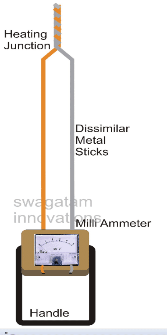
The following examples have explained how the phenomena takes place:Consider two dissimilar metals, copper and aluminum.
Let the metals be formed into loops and joined at their ends by twisting as shown in the figure.
Now as explained above suppose one of the junctions is heated, keeping the other junction at room temperature, the flow of current can be simply confirmed by introducing a milli ammeter anywhere in series with the “circuit” or as shown in the diagram.

However, the ammeter only determines and measures the flow of current and if we want to measure the voltage or the potential difference across the wiring we will have to use a voltmeter or rather a Millivoltmeter and connect it as given in the following diagram.
Here we can see that the second junction of the above circuit has been opened and the resulting terminals are configured with the voltmeter terminals.

The above directions and principles looks pretty straightforward and an easy alternative for measuring high temperatures.
Drawbacks of Thermocouple Sensor
However, the system as one big drawback, since the entire phenomena is working and based on the temperature differences of the respective junctions, means that the introduction of any further junctions would directly affect and interfere with the actual readings of the system.
When we connect the meter terminals to the above explained thermocouple ends, the connections individually act as two more junctions, infusing two more temperature sensing points, which may either add up or deduct the readings from the actual sensing happening at the other end.
But having said that, the conditions can be rectified by keeping the meter connections as short as possible.
It means that if the meter wires are kept absolutely small or in other words if the meter is directly connected across the thermocouple ends can make the differences negligibly small and can be ignored.
Though this principle is usually avoided and the problem is rectified by balancing out the disturbance through a Wheatstone bridge network.
However with our experiment, in order to keep the complications to the minimum, we can make the proposed temperature meter by integrating the thermocouple links directly to the meter termination points.
We employ a rather unusual but very effective method of selecting long bars of the two dissimilar metals, which will help us to isolate the meter from the furnace heat to a safe distance and yet produce reasonably accurate reading of the measured temperature
How to Make a Pyrometer using Thermocouple Sensor
The following explanation will illustrate the whole procedure to you:
You will require the following materials for making the discussed furnace temperature meter:
- Copper and Aluminum sticks – 2 and a half feet long each, half centimeter in diameter.
- Ammeter – 1 mA, FSD, moving coil type meter.
- Wooden block with handles, drilled appropriately with through holes for reinforcing the metal rods.
The following procedure explains how to make a thermocouple or a pyrometer Circuit.
Pyrometer Construction Procedure:
Using a sand paper clean of the metal rods gently so that any carbon or corrosion layers are scraped of, and the metals are made shining clean.
Using a pair of nose pliers, carefully bend the metals at certain angle (as illustrated in the diagram) and twist the ends firmly with the pliers.
At this state the rods will be in a quite vulnerable situation and will need to be reinforced at the free ends, so that the junction doesn't disintegrate.
It is done by guiding the rods gently across the holes of a well dimensioned wooden block; the drilling must be selected such that the rods go snugly through them.
The meter now can be appropriately fixed over the wooden block itself and the rod ends also connected to the meter terminals.
Since the attached meter is an ammeter, will require an appropriately calculated resistor across its terminals, so the voltage across it may be translated into a readable potential difference or a voltage corresponding directly to the temperature sensed at the extreme end of the thermocouple.
The meter scale will also need to be calibrated linearly as per the corresponding temperature indications.


Comments
Swagatam sir,
Does cold junction compensation not needed. Because thermocouple gives only difference in temperatures and your ammeter reading will show value to which room temperature has to be added. Kindly clarify.
Premila, yes that’s right, we can perhaps roughly tackle this by calibrating the meter for different room temperature ranges, and then roughly get the idea of the respective readings for those sets of ranges while practical implememtations.
By the way please provide me your phone number asap so that we can complete the packaging formalities of the Arduino kits and send it to the specified address.
We tried to contact you through emails, but couldn’t get any response so far from you.
Can you suggest me a nice op-amp circuit for that purpose, by the way, Can I use 2 npn transistor amplifiers, and obviously I guess that the voltage for the transistor collectos must be 5 Volts so the millivolts of the thermocouples can be scaled with the 5 volts. I want that, whenever the temperature is higher it shows 5 volts and that scale
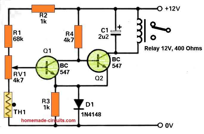
you can probably do it in this way….take a 4 or 5nos BC547 transistors connect the 1st transistor's emitter with the second transistor's base….second emitter with third base and so on, and connect the last transistor's collector to the relay driver stage.
the thermocouple could be connected across the base ground of the first transistors
an example can be viewed here
http://www.talkingelectronics.com/projects/BasicElectronics-1A/imagesP1/Fig53-%203Transistors.gif
I want to connect an industrial thermocouple to an arduino and then use serial and basic code to regulate whenever it goes beyond an expected point it goes high or low in any out pin. The question is is it possible to connect to analog in without exposing to burn, as I know thermocouple only shows a Mili Volts signal
I think you may have to amplify the voltage using an opamp circuit and then you may integrate it with the following concept…next, you can use the selected LED output pin with a transistor relay driver for the required switching of the heater
https://www.homemade-circuits.com/2016/11/battery-level-indicator-circuit-using.html