Nowadays probably all of us have a spare cell phone charger lying idle in our cupboards or table drawers......so wouldn't it be a great idea if we could employ it like a super bright 1 watt LED driver and illuminate our room with white cool moon light.
Circuit Concept
As we all know that a 1 watt LED consumes about 350 mA of current and is capable of generating intense blinding white point lights. If this little high bright light source is enclosed within a reflector cabinet consisting of mirror finish lens, the light from it can be enhanced to great levels.
However a 1 watt type of LED would require a suitable constant voltage power supply for illuminating safely with the specified outputs.
Though there are a number of suitable drivers which are available in the market, a cell phone charger can be ideally used for this purpose.
If we look at the diagram given below, we see that the whole thing can be configured using just a single current limiting resistor.
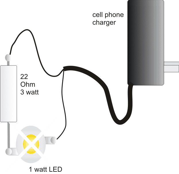
I have explained regarding the involved making procedures with the following points:
You would require a standard cell phone charger.
A 1 watt LED/350 mA white.
A 22 Ohm 3 watt resistor,
An aluminum heatsink, as specified in the given text.
Small piece of general purpose PCB, about 1 by 1 inch.
Construction Procedure:
Since the LED would be generating considerable amount heat, a neatly fabricated aluminum heatsink would be required to be integrated with it so that the life and the efficiency of the device is maintained for many many years. Please see the below given diagram to know the basic heatsink design, the holes must be drilled just as soecified in the diagram and the LED leads should not touch the heatsink while it is passed through the holes and soldered over the underside PCB pads.

A small 1 mm square piece of aluminum cut into 1/2 by 1/2 inch would just suffice.
Drill the holes into the above metal, as shown in the below given diagram and fix the heatsink over the PCB using small 1/8 x1/4 screw nuts.
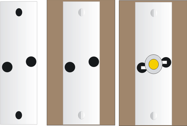
Next fix the LED over the heatsink in between the two center holes, and solder it leads with supporting copper wires such that it becomes locked with the underneath PCB pads. Be careful not to short the leads with the heatsink metal.
Connect the 22 Ohm resistor with one of the leads of the LED, preferably with the positive lead.
Finally, connect the cell phone charger wires to the resistor end and the other free LED end.
Make sure the polarity is correct while connecting the wires t the LED, identify them using a digital multimeter before doing the connections.
Your cell phone charger powered 1 watt LED lamp is ready, place it neatly over some corner of the room, plug it in and experience the awesome illumination, dazzling the entire premise.
Optionally the unit can be fixed inside a halogen lamp reflector for enhancing the light intensity many folds.
Making a 1 watt LED automatic emergency light circuit
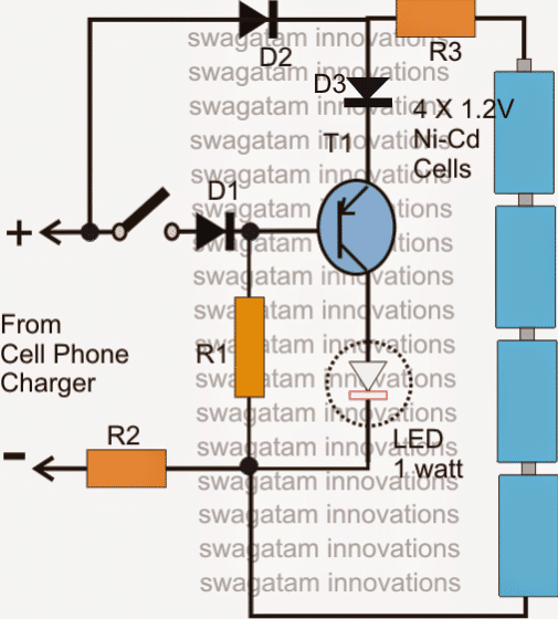
As suggested by Mr.Amit (see comment) the above concept can be very simply converted into a nice little emergency light circuit, let's see how it is done:
Referring to the figure below, assuming the voltage from the mains operated charger input to be present, and the switch in the closed position, T1 is held reverse biased so that it is unable to conduct and the LED remains switched OFF. At this position the batteries are trickle charged through R2, R3 and D2.
In case the mains fails, T1 instantly conducts and switches ON the LED automatically and vice versa.
Now suppose during the presence of mains the switch is turned of, T1 instantly switches ON, however now the LED lights up through the charger voltage (mains) while the batteries still continue to get trickle charged without getting drained through the LED.
Parts List
- R1= 100 Ohms, 1/2 watt
- R2 = 47 Ohms, 1/2 watt
- R3 = 22 Ohms, 1/2 watt
- D1,D2,D3 = 1N4007
- T1 = 8550 or 187, 2N2907
- LED = 1 watt, 350 mA, high bright
- Battery = 4 nos. Ni-Cd, AAA



Questions & Answers
I think you Require Charger with output of 5v 2a (5v x 2a = 10w) you can add 10 1w led in parallel, add 1ohm 5w or 7w resistor between battery (plus) point to led (plus) point.
You will also need a current limiter then, using LM338 or transistors.
Dear Swagatam,
What if connected 22 Ohm 2 W LED instead of 3 Watt,and can i use blue LED instead of white led ?
Sir can i use mobile charger 5v 500ma output for 10w smd rgb led with rating 10v 300ma
I have 2 spare mobile chargers…„ input 100~240v 50~60Hz
and output ¬
1st- 5.7v/800mA
2nd- 5.2v/400mA
I want to illuminate 1 or 2-3 (in parallel)…„ 1w LED/s with high brighten illumination.
Please suggest how to connect.
I am novice hobbyist.
Thanks & Regards…„
correction: use 10 ohm 2 watt resistor in series with each of the LEDs
you can connect two 1 watt LEDs in parallel with a 6 ohm 2 watt resistor in series with each of the LeDs.
battery voltage is 4.8v at 600mAh.and also it is mentioned as 1.1 watt bulb on details.above ive mentioned wrong power ratings.
600mAH will not be enough for two 1 watt LeDs not even for 1 LED
hi bro,i want to power two 1 watt LED's from a rechargable torch(2.7 watt) initially it had a 4.5v standard bulb.so which is the suitable driver circuit for LED's.
Hi charan, please specify the battery voltage and AH rating. I'll try to figure it out.
sir i buyed 4*5watts LED bulb running with cell charger.at first it works good but after 30mins 2 LEDs gone turned off i dnt know why! iam new to electronics and plz suggest me what do i do now to solve this problem.
SP, did you attach a heatsink with the LEDs? and you must also make sure that the voltage of the LeDs match with the charger voltage or vice versa….if not then you must incorporate a regulator circuit in the middle.
pls tell me, how to connect two 1 WATTs LED with 6V, 4.5 Ah battery..
It's OK…4.5AH will provide around 8 hours back for the LEDs
and LED's maximum Current 350 mA, but battery's current 4.5 Ah.
connect them in series without any resistor….but use a heatsink with the LEDs.
Irshad, the changeover action is automatic in the above circuit, but not the charging…charging system is very crude and not so reliable.
you can try the following circuit for 12V operations, replace the shown 6V batt with 12V batt:
https://www.homemade-circuits.com/2011/12/cheap-emergency-light-circuit-diagram.html
Sir,
This is Very Good Auto Charging Circuit.
How can i use this Circuit with 12 volt battery,
i have 12 volt transformer to charge the battery.
i have 12 volt Light Bulb.
now what the components value should be?????
i am waiting for your reply
3 in series might not work through a mobile charger, 2 nos would be OK.
please sir tell me , how to connect 10 x 1W LED with mobile charger (for highest brightness)
that's not possible, mobile charger will not support 10 watts
sir, can i make bulb with 1w LED, and have brightness equal to 35w tubelight.
please tell me.
Inderjeet the output is normally 8V, 500mA, it will allow a single 1 watt LED to be driven comfortably.
formula for resistor is
R = (supply – LED voltage) / LED current
sir, how many output (volt & mA) from mobile charger, and how connect one 1 watt LED to mobile charger, which register will need. and how many total power consumed. and ..please tell me formula.
Inderjeet, you'll need at least 40 to 50nos of 1watt LEDs to produce a 40 watt tube equivalent light….
dear i want to drive 10 or 20 1 watt LED by Nokia standard cell phone charger then what will be the modification of above circuit. how much the circuit is safe for continuous use?
Dear Saeed, that's not possible, a cell phone charge may not be specified for handling 10 or 20 watts of power
sir i made this circuit but in presence led still off only in presence of battery they on even after battery remove and supply is on led off. I check voltage at base point when supply is on & battery remove 4.44v & at emitter 4.34 at collector 0.22v and on other hand when battery connect and supply is on at transistor base , emiter & collector 5.5, 4.45 & 4.41 volt resp. and led glows where i have mistake
If you are referring to the emergency light circuit, then surely the LEDs will stay switched off when mains is present and switch ON when it's absent, it's exactly designed for that
i have samsung 4.75vol & 0.5amp charger. and another question what happen when cell get discharged full means any damage to battery?
Hi sir
can we use 5mm LED instead of 1watt LED in series?
If yes what is max & min no we can place in series and any resistor should use?
Hi Ashok,
I have explained it here:
https://www.homemade-circuits.com/2011/12/using-cell-phone-charger-for-making-led.html
Swagatam,
The base is switching the LED off when connected via Base (when no connected to the battery) as you suggested but if the battery is connected than the LED comes on, I have made provisions for switch in the battery +ve.
However I am getting another problem in Battery charging, I am not able to charge them beyond 3.2v to 3.4 v even when circuit is on for 24 hours, I have tried 3 times with different batteries, and every time I charge them up using a conventional charger up to 5.2-6.0 and connect them (LED brighten up) after few hours the charging drops to 3.4 but never below this.
If I use a high amp charger 6v/600mA or 7v/800mA than the brightness improves a lot but I am not sure if this will damage the circuit (I know that 8550 is rated for up to 1..5A) but still wanted to ask you that what is the maximum current I can pass through this circuit that Batteries can be charged up to 6.0 volts or full.
Regards
Gopal
Gopal, try Increasing the base/ground resistor of the PNP transistor to some higher value until the LED stops glowing… even at 4V from the battery.
This mod will also allow batt to get fully charged
Swagatam, Not sure of what Potential means here… Load is 3.3 volt LED at 350mA and the charger current is 5.2 v at 500 mA, the batteries are four 1.2 V with 1000maH.
As per the circuit the current is fed to base (Switch is on – connected) and Emitter via diodes and output is being measured at battery terminals as 3.1V.
Please suggest if we can do something to improve the LED illumination?
Gopal,
check the base voltage of the transistor by keeping red prod on base and black prod on negative line….this should be greater than the battery voltage.
Swagatam,
Thanks for the response,I have added the diode in series but still the led does not turn off completely and still stays on(when batteries are connected). The conditions are exactly same n led is always on if switch is on and when off it turns the led more bright.
However the LED is not at its full brightness and is rather dimed. Can we please make some modification for it to be driven at full brightness as even after 24 hrs the LED is not getting hot
Sorry about pestering you with questions but I am into my third circuit now.
Regards
Gopal
Gopal, according to the rules, a PNP transistor will shut off on receiving a positive potential at its base which may be slightly higher than the load potential.
Please confirm the above in your circuit, otherwise the leds will keep glowing dimly, even during the presence of mains input..
Swagatam,
I attempted twice to make this circuit, here are the things I used:
Cell phone charger – 5v/ 600mA,
old rechargeable cells of 1000mah,
S8550D – PNP transitor (when flat face towards you- pins are emitter, base, collector),
When I assembled the kit-checked charging and all is fine and the batteries are charging, after a short while…. the LED starts to glow and is not turning off even when switch is off, when switch is turned on the LED dims but still kept on glowing and in fact glowing till now. Initially i thought I had the wrong pins on transistor but I have tried 3-4 pieces all giving me same results. Please help.
I need this circuit to help build a basic lantern to be given to few people in my village as I want it real cheap. I have the red lantern kits lying around with me except the circuit and battery 🙁 and I am struggling to give them something robust for use
.
Regards
Gopal
Hi Gopal, with the switch in an open position the LEDs will naturally get switched ON and will stay switched ON, unless the battery is removed.
The emergency lamp is designed to work in that way, it will stay switched off as long as the transistor base is applied with a potential.
add one diode in series with the emitter of the transistor, the LEDs will be switched OFF completely in the presence of mains input.
for preventing the battery from getting discharged you an add an ON/OFF switch in series with the positive of the battery and use it when the unit it is not plugged in.
Gopa, a laptop charger is normally specified with 19V/2amps, means you can accommodate 19/3.3 = 5.75….. around 6 LEDs in series and 2/.3 = 6.66….that's around 6 of those series in parallel…
6 strings in parallel each having 6 series LEDs…no resistors required
Thanks Swagatam, I am getting confidence in my calculations 🙂
please spare few mins and let me know how many LED all 1 watt can I use with laptop charger.
Thanks
Gopal
Gopal, yes that's correct, I seem to have calculated them in a hurry
Swagatam,
In the first part shouldn't it be 6.6 Ohms as 18.5- 16.5 (3.3*5) = 2 divided by .3 will give you 6.6 Ohms and .6 watts…
Sorry if I am wrong but I have 2 spare chargers and now I am encouraged to make a light with them… What is the maximum number of LED's I can use with 18.5v/3.5A?
Thanks
Gopal
Hi,Thanks In Advance the Possibility of using Rechargeable flashlight transformer which input 220-240v 50-60Hz and output DC2.4v .3A .72v can we use this as led driver.please Suggest
A basic LED driver can be made simply by a using resistor in series with the LEd, so with that consideration yes it can be used.
Hi, I have connected 3*1 W led in parallel with 5.6 ohms resistor with each LED but only one led working please guide
check the polarity of the LEDs, they could be wrongly connected