Ever needed an application where the resistance of a resistor needed to vary proportionately in response to a PWM or a varying analog voltage?
Yes, this is where an LED-LDR opto-coupler becomes so useful.
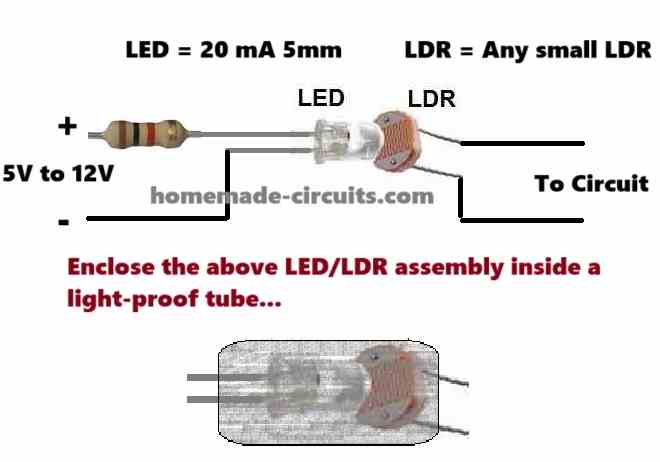
The following image shows the symbol for a LED LDR opto-coupler.
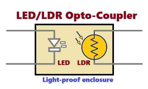
Any other regular opto-coupler, such as an LED/transistor, LED/FET, or LED/Triac type opto-coupler, would completely fail to implement the above working.
An LED-LDR-based opto-coupler can be very easily built at home by concealing any standard LED and an LDR inside a compact, light-proof tube.
If you do not want the read the following description, you can watch it in the following video instead:
Construction
I have explained how this can be done using the following procedures:
To build this LED-LDR opto-coupler, you can use any standard 20-milliampere, 5-mm type LED; the color of the LED does not matter.
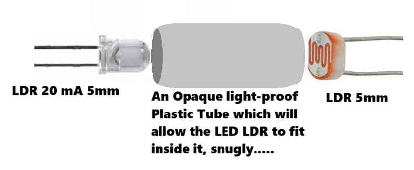
The LDR can also be any standard 5-mm-type LDR.
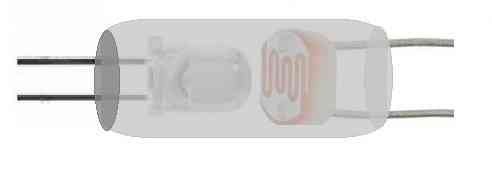
Next, you just have to insert the LED from one side of the tube and the LDR from the other side of the tube until they are both face-to-face at touching distance inside the tube.
After this, confirm whether the assembly is working correctly or not. To do this, take an ohm meter with its range selected at above 1 megaohm.
Next, connect the LDR terminals with the probes of the ohm meter. The meter should read in megaohms or near infinite resistance, proving that the LDR is not receiving any external light.
Now, connect the LED terminals with a 5V or 12V DC supply through a 1k 1/4 watt resistor. Make sure the supply polarity is correctly selected.
This should instantly illuminate the LED inside the tube, causing the LDR resistance to drop to around 10k.
The ohm meter should now display a resistance of anything between 1k and 50k.
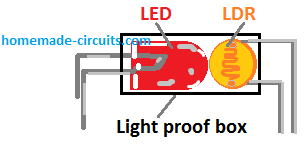
Once the above is confirmed, you can seal the terminal ends of the tube with epoxy glue and let it dry until the epoxy is cured and hard.
You can further confirm the working of the device by applying a varying voltage to the LED terminals via a 1k resistor or by feeding a varying PWM. Doing this should cause the LDR resistance to change proportionately.
Your LED-LDR optocouple is now ready and can be integrated with any desired application that requires a resistor value to change proportionately in response to a varying DC voltage or a DC PWM.
If you have any related doubts or queries, please feel free to comment below for quick replies.
Discussing the use of Optocoupler using LDR/LED
My good friend, Mr. Chiverton, shared his experience regarding the features of an LDR in comparison to phto-transistors for making opto couplers. I have explained what he discovered regarding optocouplers during his experience with my ghost detector circuit.
So far, I've only done indoor testing, and the ghost detector circuit responds as if there is some residual static charge buildup on some things around here in the house we live in, but then for a charge buildup, there has to be an opposite charge somewhere for another object to gain the opposing charge.
It makes me wonder if these so-called orbs that we cannot see actually leave any static traces to or other things. I've yet to do more tests and take notes, which I will forward to you if using the trigger coil tester as a relay status indicator. Remove any diode across the relay inputs; otherwise, only one of the leds in the trigger coil tester modified as a relay input status indicator will blink.
The diodes and circuit of the trigger coil tester may resume their role as a diode in themselves if they do. Also, the end of the trigger coil, which is not connected, acts as an RF transmitter with a with a short range, which can be picked up by the ghost detector circuit. Just thought I would let you know.
Also, photo transistors, the 3 leg types, are no longer on sale at any electronics stores here, but there is a 2 leg photo transistor, but infrared type only, so I will update the ghost detector to use the photo interrupt, which sells still, as my last few fair child photo transistors will soon be used up for making the home-made optocoupler circuit for the ghost detector.
Hi Steven,
That was a good discovery; I will put the whole thing out there.
Thanks, and keep up the good work.
I look forward to hearing more from you.
Swagatam.
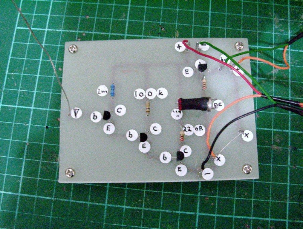
This is an upgraded 6 million gain circuit using the Swagatam buzzer circuitry. Unfortunately, my last 2 rare Fairchild photo transistors didn't work, so I put in this metal body photo cell with a built-in lens, and it works but is very sensitive at detecting static charges. Like the first 6 million gain circuit, the LED on it responds to static charges up to 11 feet away, so that's very sensitive.
In fact, its sensitivity beats the ridiculously sensitive charge detector circuit by a mile, as I also built it and tested it, so even though all the ghost detectors also sense static charges, they are still ok at sensing ac fields. And most sense the body, energy fields, or aura, as this 6 million gain circuit does it well, especially when you move your fingers when holding the box it's housed in after letting your energy warm the box for a bit.
Hi Steven, Thanks,
When it comes to sensing light (as in our opto-coupler), I think LDRs are more efficient. Moreover, they are easy to handle and much cheaper.
I have had good and long experience with LDRs and found their work to be wonderfully well done.
Thank you, Swagatam.
I've just finished testing all my LDRs, even the large one on the buzzer circuit built separately, and not one of them works for me, which is strange considering I have never used these LDRs yet, not for years.
When I measure them on my multimeter, they register as 1k in the dark state, and when I put light on them, the resistance jumps to above 6k. If I use them in the separate buzzer circuit, the buzzer sounds loud with light shining on the ldr and also sounds loud still when they are dark.
At least 3 of my ldrs make the buzzer sound alter only slightly when I move light to it and away, but thus still sound loud and never silent, even loud when I cover the ldr to block out all light.
Hi Steven,
Sorry, but I don't quite agree with you.
There's definitely something's wrong, either with your LDRs or the procedures. I have used LDRs in many of my projects; these devices are wonderful.
Please do the following steps to check the LDR response:
- Take the LDR, connect the multimeter prods to its legs, and hold it firmly with your fingers. Let the ambient light fall over the LDR.
- The meter will obviously show certain low value. Now shift the "face" of the LDR somewhere towards the darker side. You should immediately see a change in the reading of the meter (increased resistance).
- Make the LDR face different light intensities by manually shifting its direction. The meter should display different corresponding readings (resistance values).
- This will convincingly prove the correct working of the LDR. Also, at complete darkness the LDR should show INFINITE resistance.
- If these conditions are not met, then definitely your LDR is a faulty one.
- Once the above correct functions of the LDR is confirmed, now you may configure it to the opto coupler. Also remember the opto coupler should be housed inside a PERFECTLY LIGHT PROOF ENCLOSURE, otherwise it will behave erratically and produce wrong results.
Thanks swagatam
I'll retest the LDRs again and let you know. What are the chances of all of my ldrs being faulty? Even though I haven't used them all up in all the years I've had them, they've been sitting in my parts drws for so long. I'll get back to you. I'll also test the transistor for the buzzer circuit and see if that's ok with your right swagatam.
I underestimated the LDRS supersensitivity. First, I blocked all light from it using my fingers in a room that has some light in it, and tonight I did a better test with the window blinds closed and less light.
So I was in darkness, and the buzzer circuit that I ran the ldrs to was OK. The transistor tested OK, and the buzzer in the dark died down to nil in the dark, so it wasn't faulty after all, but the only failure I got was my largest CD photocell or ldr. In the dark, the buzzer was still sounding.
When I applied light to it, it got louder. Also, using my finger to block light wasn't so useful after all, as even the light at its lowest still went through my fingers, and the high sensitivity of the LDR made it easy to detect.
Still, the light has to be blocked much more from entering the ldr, especially through my glass fingers. I have some information I collected some time ago from scientists saying that parts of the hand emit light even though we can't see it. Do you think it's the case to use a finger to block light when it emits invisible light and the ldr still senses it with your finger covering the ldr?
Hi Steven,
- Thanks - The theory behind the emission of photons by human hands might be true, in fact all living beings emit photons to some levels, but are too low to practically detect.
- The level of LDRs response to light is quite equal to our eyes. It simply means that any light that is not visible to our eyes cannot be "visible" to the LDR.
- As we know it is almost impossible to contain light, water and air in our hand, therefore in your experiment, its only the ambient light which is passing through your hands and not because of anything that is being emitted from your hands.
- The opto-coupler needs to be SEALED inside an OPAQUE enclosure to produce the optimum results.
Need Help? Please Leave a Comment! We value your input—Kindly keep it relevant to the above topic!