In this post I have explained about a car voltage stabilizer circuit which could be made and installed in all cars for ensuring a perfectly controlled and stabilized supply for the associated sensitive electronics and gadgets.
Understanding Car Electrical
A car electrical is probably more volatile than our house electrical, simply because it is generated from a source called alternator whose output considerably varies with the speed of the vehicle.
It means if you are driving your car with sudden changes in its speed or if you are often applying brakes, would consequently generate varying voltages from the alternator outputs.
Since nowadays our car and other vehicle interiors heavily involve sophisticated electronic gadgets, an unstable voltage conditions can cause serious effects on their performance and life.
The circuit idea was requested by Mr.Haziq, let's know more about the making of the proposed circuit (designed by me for the application).
Today we have some wonderful ICs at our disposal which are specifically designed for voltage regulation applications.
The LM317 and the LM338 are a couple of them which are versatile with their voltage regulation functions, I have discussed them elaborately in some my earlier posts.
The LM317 can handle up to 1.5 Amps while its big brother the LM338 can hold not more than 5 Amps.
However these values are quite meager when compared to the huge asks in automobiles.
By suitably modifying the configurations, the IC can be made to regulate any desired levels of currents though.
In the proposed car voltage stabilizer circuit we incorporate the IC LM317 and modify its standard design such that it enables the car electrical with sufficient power and yet restricts it from all possible dangers like overloads, over current, fluctuating voltages and short circuits, providing an ideal voltage conditions for the vehicle interiors.
Circuit Operation
The circuit diagram shows a rather simple configuration where the IC 317 has been wired in its standard voltage regulator mode.
R1 limits the surge current, while R2 decides the triggering voltage to T1, if the current consumption crosses the 1.5 amp mark, T1 conducts and assists the IC by sharing the excess current through it.
P1 is set for achieving around 13 volts across C3.
R5 monitors over load conditions and short circuits, if the current crosses beyond 12 amps, sufficient current develops across R5 to trigger T2, which instantly switches OFF the IC so that the output voltage drops and restricts the current below 12 amps.
Ideal Specifications:
- Constant voltage = 13 volts
- Current Limit = 12 Amp
- Overload protection = above 12 amp cut OFF
- Thermal protection (if the transistor and IC are mounted on the same heatsink with mica isolation)
- Short circuit protection (fire hazard protection)
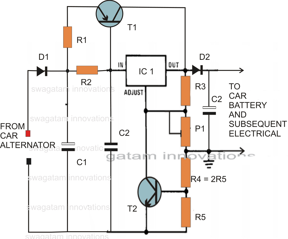
Parts List
- R1 = 0.1 Ohms, 100 watts, made from 1mm iron wire.
- R2 = 2 Ohms, 1 watt,
- R3 = 120 Ohms, 1/4watts,
- R4 = 0.1 Ohms, 20 watts, as explained for R1 (this resistor is actually not required, may be replaced with a wire short.)
- R5 = 0.05Ohms, 20 watts, make as R1
- T1 = MJ2955 mounted on big finned type heatsink
- T2 = BC547,
- C1 = 10,000uF, 35V
- C2 = 1uF/50V
- C3 = 100uF/25V
- P1 = 4k7 preset,
- IC1 = LM317
- D1, D2 = 20 amp diode (3nos. 6 amp diodes in parallel)
Simplified Version
Using the IC LM196, the above configuration becomes extremely simple, you may refer to the following diagram which illustrates a simplified version of the proposed car alternator voltage stabilizer circuit using bare minimum components.
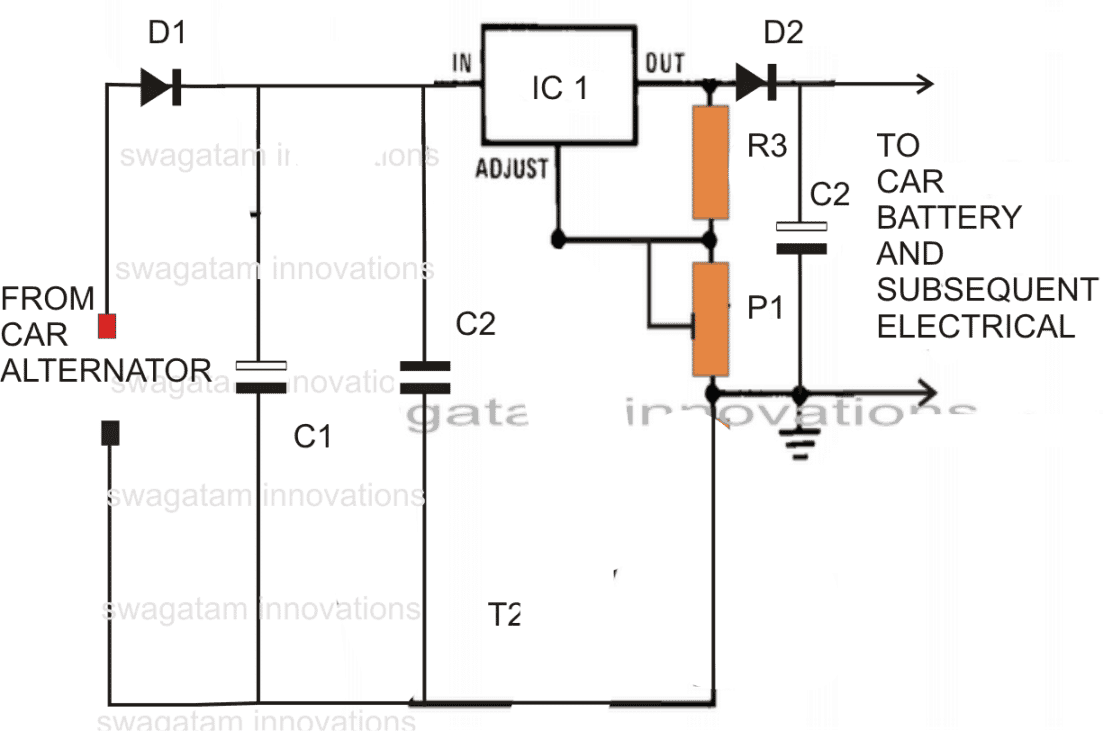
- R3 = 240 ohms
- D1, D2 = 15 amp diodes
- P1 = 10k preset
- C1,C2,C3 as specified above
- IC1 = LM196


Questions & Answers
Is there a way to have a led bulb in this circuit to make sure that it’s on and working?
You can put an LED with 1k in series, across the C2 to indicate the output is ON, however this will not guarantee if the regulator is good and regulating the voltage to set level, for that you may have to put a voltmeter across C2…
Hi, great post. I want to stabilize my out voltage of my car to 12v, but my alternator varies from 13 to 14.1 v, and i want 12 amp. How i suplie the voltage in the input for the output has 12v stabilize
Hi, thanks! I would recommend you the following simple circuit:
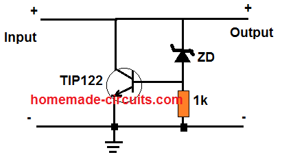
The TIP122 can be replaced with TIP142 for higher requirements.
First of all a lot of greats for the help. This design doesn´t work for me because i need this:
– I have in the input from the battery of the car between 12.6-14.2 V
– And I need in the output 12 V stabilize and 12 AMP.
I think in a dc-dc converter but I not have the sufficient knowledge of electronics to design myself one
Hello, whats the value of the voltage entry is 13V or is the output?
The input voltage can be up to 20 V…the output can be upto 14 V DC.
Hello, can you show something about make resistor from iron wires, i’ve searching for it, but i’m not having sucess with it.
You can take a thin iron wire and bend it in a zig zag manner…this will turn it into a resistor. The value will depend on how many zig zag bends you have on the wire.
Should You have a schematic diagram over a triple phase inverter from 12 – 24 volt Dc to 400 volt Ac I would be most interested to view it?
Jan, you can perhaps use the following concept presented in the following article:
https://www.homemade-circuits.com/3-phase-solar-submersible-pump-inverter/
Hwoever for the 400V conversion you will need a 3 phase transformer at the output
Hey Swagatam,
Good day to you mate.
I have had problems with my vehicle’s alternator before, wherein it would output a much higher voltage than what is necessary (16-18 volts, instead of the normal 13-14 volts). So I think the voltage regulator built-in on the alternator got damaged or is already defective.
1. Would this voltage stabilizer you made, be of benefit to me, if I use it on a completely working alternator, I’m Just going to use it as an assurance that if ever somethings goes wrong with the alternator again, my car’s gadgets and other electricals/electronics won’t be damaged?
Would that be fine to use?
2. Also, if I use your voltage regulator along with the defective alternator, to regulate the voltage that goes thru the car’s electricals, would that be a good idea?
3. Lastly,
I would like to print out a custom PCB for this, what would you recommend the thickness of the copper be? and the overall size of the PCB that includes the heatsink?
4. should this be in the car’s hood or inside the car itself? Can it withstand heat if the car is parked under direct sunlight?
Thanks in advanced. 🙂
Hey Rich,
Yes definitely you can use this highly reliable LM196 design to limit the voltage below the mentioned level and limit the current to below 10 amps.
However. whenever an alternator is involved it is recommended to apply a shunt based regulator or a parallel regulator and not a series regulator as this. A shunt regulator grounds the excess power from the alternator thereby reducing the high voltage build-up in the alternator winding, and safeguard it from burning o heating up excessively.
Using the above concept might protect your car electrical without any doubt, but I am not sure about the alternator.
No this circuit cannot be used inside car hood, since the IC needs proper cooling otherwise it might go into a shut down mode.
THe thicknes of the copper pad across the input and output lines can be 1 cm thick with thick solder layer poured over the entire track route.
Hello!
What if I want to it to be able to provide 60A? Should I add some more transistors like T1?
For 60 amp regulation you can try applying 3 parallel p channel mosfets IRF9540, and increase R2 to 10 ohms, and replace R1 with a wire link
Hello,
Your regulator is supposed to work with 15 volts in, what would happen if it gets less than that, say, 12.5v? Or less than 12v?
It will continue to conduct and allow the lower voltages to reach the load
Thank you. In other words there is no voltage drop between the input and output voltage?
The circuit is about controlling alternator voltage which will be mostly at 15V when the vehicle is running.
Thank you for your reply. I just want to make sure that the circuit would provide at least 11.5v when the vehicle is off and it would run on a battery power for a short while
Now I understand my source of confusion. I was thinking to use the regulator only to power up my carputer (which requires 11.5-12.5v @ no more then 10 amps). But your circuit is designed to replace the car regulator which would provide 13 v with alternator on and battery voltage when it is off. However, I’m reluctant to alter the car circuits since they work perfectly. Do you think it would work if I only use it to stabilize the voltage to my device? Or what would be the best way to go about it?
Yes, no need to add this regulator if your existing alternator regulator is working OK. If you use this regulator after the battery then it might not be suitable because the differential should be around 3 V, meaning the input must be 15V to produce 12V. The best way would be to add a few 6A4 diodes in series with the device positive line, that would restrict the output below 13V
No problems! The actual purpose of this circuit is to provide a regulated charging supply to the battery… it’s the battery that finally supplies all the power to the car electrical.
Hi Swag,
Th input Line Must be alternator or, it can be a battery line.
coz I was looking a 12V stabilizer too. May be my idea is wrong. Just give me a advice.
I have a chicken farm in a village no electricity there.
I just fix a Solar Panel 150W and 100A battery. Aim using mostly it on night time only. Day time iam using one or 2 fans.
i don’t connect any Inverter . Using direct 12v.
4 DC ceiling fans (36W) and 13 LED strip ( each led strip is 12V 20W). My problem is if I switch two or three light its ok. Once I switch one any one or 2 fan then lights will be very dim. If I switch off the fans or some lights then rest of lights are very bright. So i fix this stabilizer my problem will solve or is there any other way to solve this problem.
I just want to use fans 12 hours per day. all lights 12 hours per day too.
Regards.
Hi Paaker, Voltage stabilizer has no role here. You must make sure that your total consumption does not exceed 150 watts, that’s 12amp current, otherwise your battery could start discharging at a faster rate and show a voltage drop quickly.
And please check and confirm the consumption with an ammeter because if one of the gadgets is malfunctioning can result in unnecessary wastage of power.
If you want to solve the problem correctly, you may have to employ another battery in parallel.
Hi Swag,
I have fixed some digital voltage ampere between fans and lights. if I switch on all lights and fans on full speed, then my meter show 12.2v 6.2A. this is the usage if iam switch on all the gadgets at onetime.
Hi Paaker, the ammeter should be in series with the battery positive terminal, connect the ammeter positive with battery positive, and connect the supply to the rest of the load from the ammeter negative.
really!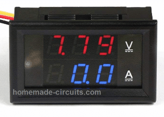 ) on this meter Batteries Negative was sears between Battery and gadget.
I was using Digital Volt amp display (
You can connect it in series with the negative line or positive line, that is not crucial….but it should be in series with the one of the power lines…
Can i use this circuit to my 110cc motorcycle?
yes you can!!
it is 1/4 watt
your project are very educative and i want to please use component like crystal in your project so that we can understand their usage in oscillation.thank you sir..
thank you, I'll surely consider your request.
In your circuit there are input and output, how to change this circuit so we just have 2 wire connected to – & + battery?
actually the (-) of the battery and all the loads could be made common and joined to the car chassis….only the positive from the battery needs to be connected with the input (+) of the circuit and the output (+) from the circuit can join with the car gadgets for powering them with the desired stabilized supply
the input side needs to be connected to the battery (+)(-) and the output side with the load or whatever electrical/ electronics you may be having in your car….briefly, the circuit should be in the middle of the battery and the car electrical units, the supply needs to pass through the circuit before reaching the car gadgets.
How will it effect my voltage regulator in my motorcycle?
It will work good in your motorcycle as well.
This looks like what I've been shooting for to stabilize the system voltage in my truck. Is your circuit designed to connect in parallel to the charging cable, or in line so all system current passes through it?
It depends whether you want to stabilize the entire electrical of the vehicle or just a single gadget. If it's the entire system then the voltage must pass through the circuit, if it's for a particular device such as a battery, then it could be positioned in between the source and the battery.
However the above circuit is applicable for 12V vehicles only, if your truck operates at this voltage then you can try the second design in the above article.
Hi, Thanks for your advice.
1. Does it make any difference that a dynamo and not an alternator is being used in my case?
2. Does the ideal specification you quoted, particularly the current overload protection, apply.
3. Can it safely handle the continuous load of 6 to 7amps?
more info about the IC can be found here:
https://www.homemade-circuits.com/2013/04/15v-10-amp-adjustable-voltage-regulator.html
yes a heatsink would be required for the IC for efficient working of the device.
1. It won't make any difference.
2.you will have to include T2, R4, R5 stage as shown in the first circuit for getting the current control feature, if it's absolutely critical.
3. LM196 is rated to handle upto 10 amps, so it's safe.
Hi, I have an old car that has a dynamo with only a standard cutout. i.e. no voltage or current control other than an adjustable third brush in the dynamo to control the maximum current output to 11 amps. When the battery is discharged following starting the maximum voltage generated for a short period is about 17 to 18 volts.
I want to use an electronic ignition system and this is designed to operate between 8 and 16 volts. I would like to put a voyage stabiliser in the positive feed to the ignition to control at about 13 to 14 volts. I estimate that the amount of current taken by the coil and electronics would be 6 to 7 amps. What circuit would you advise please to very robust under these conditions.
Hi, Thank you for your reply.
Doe the fact that I am using a dynamo rather than an alternator make any difference to your recommendation?
Does the ideal spec you quoted at the start apply to this circuit?
Will it handle the continuous load of 6 to 7 amps and does the ic need a heat sink?
You can try the last circuit shown in the above article using IC LM196. According to me this will perfectly suit your needs.