The following article discusses a few very simple intrusion detector circuits, or ant-theft alarms. The presented designs are easy to build yet extremely effective with the functions.
How the Circuits Works
An intruder alarm basically consists of a sensor and a trigger stages, which work together to produce the required detection.
The sensor detects the presence of an intruder while the triggering stage responds to the sensor detection by instantly raising the alarm.
The triggering stage may consist of a voltage/current amplifier stage rigged with a relay driver stage along with a timer stage for keeping the triggering switched ON even after the threat is eliminated, for increased safety.
The sensor pat is generally more sophisticated because it's the main section responsible for detecting the threat.
Generally infrared sensors which work by detecting body warmth are incorporated in most hi-end types of anti-theft alarms, however here we'll try to implement reasonably similar results yet use ordinary arrangements for the sensor stage in the proposed circuits.
You may also want to build this PIR burglar Alarm Circuit
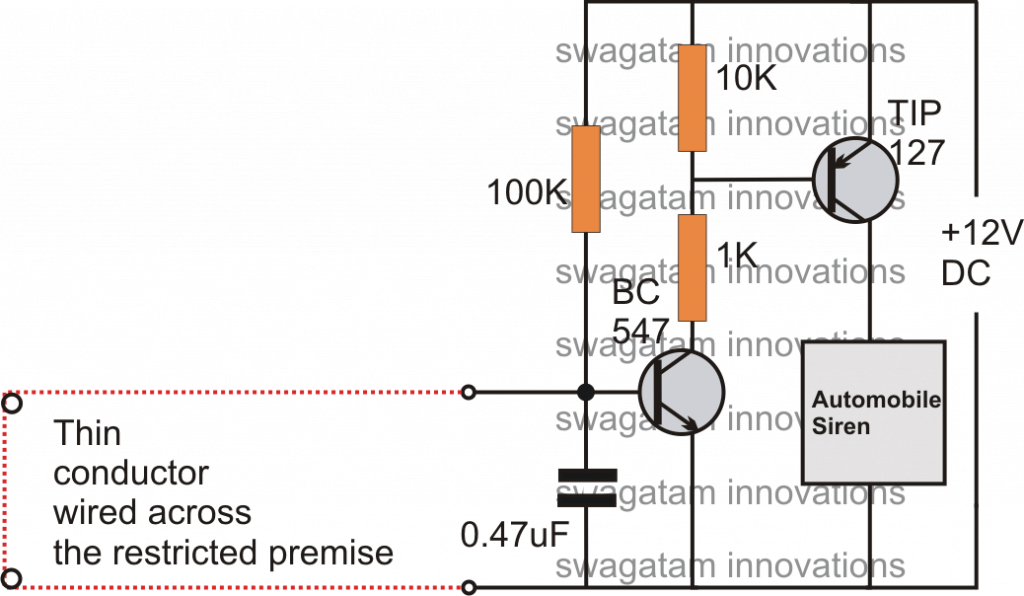
Intruder Alarm Using an Ordinary Conductor as the Sensor
This is probably the simplest one among all. As shown in the circuit diagram, the sensor is an ordinary thin wire conductor which is laid across the restricted area in such a way that anybody intruding the place gets caught up against the conductor and in the course breaks it up.
Once the wire breaks, the transistor is allowed to receive the required base drive, ringing the attached alarm.
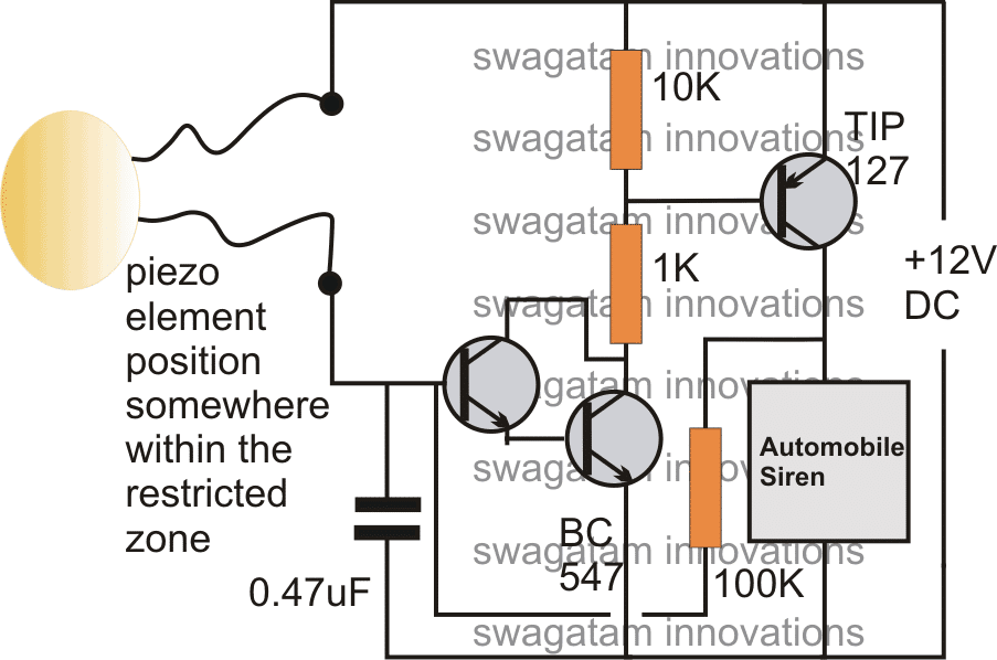
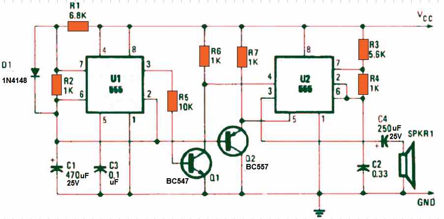
Intruder Alarm Using a Piezo Electric Sound Sensor
This circuit is based on a sound detection through an inexpensive piezo element.
The entire system may be fixed over the door or the restricted entrance. If an intruder tries to break in, the door would be disturbed instantly activating the connected piezo sensor, and the preceding alarm circuit.
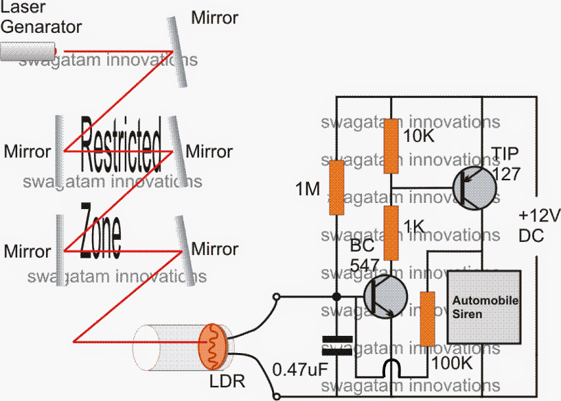
Intruder Alarm Using a Laser Beam.
Today toy laser beam generator devices are pretty popular, and can be easily procured ready made from the market.
This toy laser beam can be effectively implemented as an alarm sensor. As shown in the figure, the restricted area may be swarmed by laser beams reflected across the area via accurately angled mirrors.
The final reflection gets directed toward an LDR trigger circuit. In case an intruder tries to trespass the premise, the person would block at least one of the reflections, interrupting the laser passage over the LDR.
This would result in an instant triggering of the connected driver circuits.
Intruder Alarm with Push Button OFF Feature
The above design of a latching laser activated alarm can be modified with a push button OFF feature.
The following diagram shows how it's implemented using a single SCR, while the LDR, and the laser set up remains the same.
The idea was requested by Mr. Kuldeep
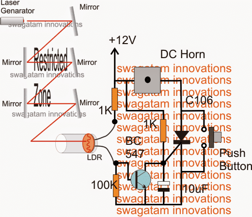
The 12V input power should be switched ON only after the laser point is set on the LDR.


Discussion & Solutions
Hello, good afternoon, I am a faithful follower of the website, in this case I want to ask you for a circuit to protect my house… Since last night there were 3 men trying to enter… Maybe a circuit that detects when a person is standing at the door After a few seconds a relay is activated… I say after a few seconds so that it does not activate when pedestrians pass by. Maybe some infrared circuit or some other method… Thank you very much in advance
Thank you Carlos,
I will try to design it soon and let you know.
Hi Carlos, I think the following PIR circuit is the easiest and most effective, however you will have to enclose the PIR lens inside a pipe and angle it such that it detects a human only when he is near to the PIR installation or the door.
https://www.homemade-circuits.com/pir-burglar-alarm-circuit/
The delay is not required because the angle of the pipe will not detect the pedestrians, it will detect only when somebody reaches near the door.
dear sir, please do not ignore my comment, just help me. I am an electronics technician doing a lot of repairs of basic gadgets, and sometimes assemble simple circuits using solar panels, car batteries, TV aerial receptions and many others. My concern has has been the many posts in PINTEREST showing that ELECTRICITY can be generated using MAGNETS and COPPER Wires. My question to you is: DO THESE CIRCUITS WORK. ARE THE DEMONSTRATIONS REAL. A friend of mine and myself tries one of them, and did not even show any voltage deflection on our digital multimeter. Are we being fooled, or are there hidden tricks to the whole ideas. Please HELP.
Hello Wambua,
You can generate electricity using magnets and copper wire, which is a very basic concept. If you move a DC motor spindle with your hand it will generate electricity using the copper winding and magnets inside.
However, these systems cannot be 100% efficient.
If you find videos showing magnet motors producing over 100% efficiency then those are fake videos.
Hello, I am an accountant and I have an idea for an alarm (such aas a, door alarm or burglar alarm) to work in reverse.
That is to say, the alarm remains silent while the circuit is closed and activates when the circuit remains closed but the primary source of current is cut off.
I know it sounds silly but please humour me and tell me if you can assist me.
As I said I am a novice in electronics.
Also let me know the cost of such assistance.
Hello, It may be possible but the circuit will need to have a battery inside for it to activate when the DC from the primary adapter source is cut off.
I would like to put a light and a buzzer on the outlet that my freezer is plugged into. The circuit that this freezer is connected to has a GFI that is in a different part of the house. Several times, that circuit has been shut off because the GFI has been tripped. (I don’t know what tripped the GFI.) When the GFI cuts off, the circuit the freezer is on is turned off and things start to thaw. Can I buy or make a device that will sound an alarm and flash a light to alert me to the fact that that circuit being shut down? Can I purchase such a device or how do I make one from components? Where do I get the components to make it?
This circuit will be a battery operated circuit attached with your freezer AC mains. When the freezer AC is not available the circuit will switch ON and provide the necessary flashing and buzzing alerts through battery power.
I can design the circuit for you, but unfortunately I cannot produce the prototype for selling.
Dear Sir Swagatam
I praise you for this spirit of helping others. I have never seen a man like you during my 69 years age life. Thank you for your continuous favor . I always keep in my mind your kindness and wish you Success and health. I wish my English was so good that I could praise you as it deserves. I will do as you have instructed Sir.
Best regards
Mehrdad
No problem dear Mehrdad, I am always happy to help! And your English is perfect, I can understand it without any issues.
Ok so how to help me with a simple cicuirt diagram for theft prevention at lab
Sir Swagatam
Hello. Thank you very much for your favor Sir. I did the edited circuit and the delay was occurred but since I needed more delay, I substituted C2 and R2 with 1000 Mf and 2.2 MR and I got 90 seconds delay which is perfect and will solve my problem. Do you think these changes will not make the circuit work bad?
Thank you again dear Swagatam.
Wish you all the best
Mehrdad
That is great Mehrdad, what you have done is correct and it will not affect the circuit in any manner, except increasing the delay. You can also try adding a 1N4148 diode in series with the BC547 emitter, this will allow you to reduce the 1000uF value and still get the required delay.
Dear Sir Swagatam
Hello. I hope that you are fine.I assembled two sets of the circuit that you had suggested to me with 2 Nos of 9v relays: one of them was 8 pin 380 ohm and the second one was 5 pin 380 ohm (my mutlmeter shows this amount of resistance). I had replaced T2 (BC557) of the two circuits with 2N2907A as well, and everything was good and both of them worked well until an hour ago that I needed to replace the 5 pin relay with a 8 pin one. unfortunately this one was 180 ohm; I noticed that the T2 of this circuit died after replacing the relay. I think that this has happened because of the lower impedance (resistance) of the changed relay. If I am right, would you please do a favor and kindly tell me:
1. If it is possible to increase the resistance of 180 ohm relay to 380 ohm by adding a resistor in series with the coil
2. can I use 2N2905A instead of 2N2907A (BC557)? They seem to be the same.
3. And a non relevant question: I have seen in a few circuits that 4 Nos of ceramic capacitors is placed across each of 4 diodes of a bridge rectifier in order to eliminate the hum sound of the mains supply. would you please tell me how much should be the value of these capacitors
Thank you dear Swagatam in advance
Regards
Mehrdad
Dear Mehrdad, 2N2907 should be easily able to handle 180 ohm relay, because 2N2907 is rated to handle up to 600 mA current. Did you connect the freewheeling diode across the relay coil? without this diode the transistor can burn quickly.
yes 2905 can be also used as the relay driver transistor.
the capacitors across the bridge diodes can e 0.1uF
Dear Sir Swagatam
Hello. Thank you as wide as the skies for your valuable guidance to all my questions. No Sir; I was lazy and did not connect the freewheeling diode across the relay coil. Thank you again sir and wish you all best things in your life that you have devoted most part of it generously and without any expectations to help others. I am sure that the positive waves of grateful people will definitely be effective in your life Sir.
Dear Swagatam what is your advice on always connecting a freewheeling ( I hope I used the right word ) diode across input and output of 78xx regulator ICs.
Best regards
Mehrdad
Dear Sir Swagatam
Hello. Thank you very much for answering my recent question. You are my only hope for solving my problems in the field of electronics. I am always impressed by your great favor and wish you health and success dear Sir engineer.
Best regards
Mehrdad
Thank you Dear Mehrdad, I am always happy to help. Please keep up the good work!
Thank you for your kind words dear Mehrdad, and I am glad my suggestions helped you.
For a voltage regulator, a diode across its input and output terminals is not critically compulsory, although it is a good practice to put it, since it protects the IC from a situation where the input side of the regulator is accidentally short circuited with the presence of a filter capacitor at the output side.
Sir Swagatam
Hello Sir. I assembled your first project and it works well. Thank you for your interesting circuits. I would be very glad if you could tell me how can I do a bit changes in this circuit diagram so that the relay that I put instead of automobile siren could be activated after about 2 minutes.
Wish you success
Mehrdad
Hello dear Swagatam,
Hope you are doing well.
As I mentioned before, I modified the 2 circuits according to your instructions to delay the start-up of the circuits for 90 seconds.
I added an alarm to the 2 Relays of the circuits and I accommodated 2 Nos of push button switches on a piece of prototype PCB; one to the fridge door edge and the other to the freezer door edge** so that if either of doors were to be left open as much as 0.5 cm., the alarm would go on.
I must add, my fridge already has a built-in alarm which goes on in case of the doors being left open as much as 10 cm.
I finished the circuits yesterday and must say they both work well. I thank you very much for your kind suggestions and practical circuit diagram.
Just one thing: During the spin of a few hours, I noticed the circuit alarm relating to fridge went on 3 times without the door opening.
I switched the places of the Push button switches, and this time, without the doors being left open, the alarm relating to freezer went on. So I concluded that the switches work well.
Where do you think the problem lies? The C2 between Base and ground? Or perhaps the 1N4148 Diodes connected to Base and Emitter of T1 or …?
I am in need of your new instructions Sir
Wish you all the best dear Sir
Best regards
Mehrdad
** Related Pictures will be send to your Email
Thank you Mehrdad,
I guess your comment is with reference to the following diagram:
Can you please explain how you connected this circuit with your fridge? I could not properly understand your question?
Hello dear Swagatam,
Hope you are doing well.
Yes Sir, this is the initial circuit diagram which you told me to add a 1N4148 diode between the E and the ground of T1 so that I can use small value capacitor for C2 (instead of 1000mF that I had chosen for reaching longer delay) in your fifth comment above. What I did was chosing 2.2mR for R1 and 220uF for C2 which I got ideal 90 seconds delay.
As I wrote to you before, I assembled 2 circuits comprising of 1 eight pin Relay for each (2 contacts of each Relay connecting to Collector and ground of each T2 and 2 the other contacts to the alarm).
As you will kindly see in the pictures that I will send through Email, I have made a 4 pins male socket; 2 pins of 4 go to a push button switch on one side and to the R1 of each circuit on the other.
As soon as each door (Fridge or Freezer) is left opened, the related push button contacts is disconnected (releases) and alarm will be activated after about 90 seconds.
Just one thing: During a few hours after connecting the circuits to mains supply, I noticed that the circuit alarm relating to fridge went on 3 times without the door opening.
I switched (substituted) the places of the Push button switches through the 4 pin socket which I have made, and this time, without the door being left open, the alarm relating to freezer went on. So I concluded that the switches work well.
Where do you think the problem lies? The C2 between Base and ground? Or perhaps the 1N4148 Diodes connected to Base and Emitter of T1 or …?
Wish you all the best dear Sir
Truly yours
Mehrdad
Thank you Mehrdad for the detailed explanation. The delay ON timer which I suggested you is very reliable and will never switch ON automatically unless a leakage current charges the C2 capacitor. So yes push buttons will work better since they cannot pass any leakage current to C2.
I saw your images however a schematic diagram helps better to understand regarding the circuit connections.
Hello dear Swagatm
Hope you are doing well
My last action was replacing T1 with a new one as you are aware Sir. About an hour after I accommodated the push buttons on the fridge the day before yesterday, the alarm went on without the door being left open and I remembered your golden Sentence ” Transistors can never conduct unless C2 charges fully, let’s hope the problem is solved”. I thought the problem should certainly originated from push buttons so I replaced push buttons with the type that I will send the picture of it to your Email and the problem solved for ever and now, everything is good after passing 24 hours.
I love and thank you as much as the whole world for your efforts, patience, and all things you taught me.
Best regards
Mehrdad
That’s great Mehrdad, and thank you for updating the results….. hope it will continue to work in this way permanently…
Hello dear Swagatam,
Hope you are doing well.
I deattached the alarm box and it’s push button switches off the fridge, replaced T1 with a new one, I put the whole set on a table, and placed my multimeter on the push buttons. Now, after 40 hours, the alarm has not been gone on even once; I hope the problem lied with the transistor T1, though it looks healthy.
I will let you know the result dear Swagatam
Wish you good times
Yours truly
Thank you for updating the results Mehrdad, yes the transistors can never conduct unless C2 charges fully, let’s hope the problem is solved.
Hello dear Swagatam
Thank you very much for your reply. I bothered you a lot. Please accept my excuse. I will replace T1 then C2 with new ones, and will let you know the result. I will then try drawing the schematic diagram.
Wish you health Sir Swagatam
Truly yours
No problem, Mehrdad, let me know if you have any further problems.
That’s great Mehrdad, you can try the following design to switch ON the relay after some delay, after the sensing wire is broken.
The diode across the relay coil can be a 1N4007 diode.
But sir if the red loop wire jointed before breaking it then the siren will be silent and Thief can break the wire in many pieces without being catched
I mean if the circuit sense jointing too then it will be perfect
Please assist ??
Hi Swasti,
The red wire is supposed to be well hidden so that no intruder can identify it, unless the person is somebody from your house 🙂
If you are not comfortable with this type of low tech intruder alarm, you can consider using a PIR based alarm system:
https://www.homemade-circuits.com/pir-burglar-alarm-circuit/
Hello Sir
How are you
Thank you very much for your great and interesting site. I am very interested and in need to assemble the first circuit which will be activated by breaking the wire. unfortunately, TIP transistors are rare where I live. Is it possible for you to introduce me other Nos of transistors such as SD, BD, 2N series which are more common?
Affectionately yours
Peter
Thank you Peter, the TIP127 transistor rating will depend on the alarm current, so you can select any suitable transistor that may be able to handle the alarm load.
I think a small alarm system can be easily driven using the transistor 8550, 2N2907, or BD140 instead of TIP127
Hello Sir Swagatam
Thank you very much for solving my problem.
Affectionately yours
Peter
My pleasure Peter!
Hello, am emmanuel from kenya.can you help me with a project idea on telecommunication please?
You must post your query under a related article, then I may try to help you!
I not to mention my guys ended up digesting the best helpful tips on your site and so immediately I had an awful feeling I had not expressed respect to the web site owner for those techniques. The people came very interested to see all of them and have now very much been making the most of those things. Appreciation for really being really helpful and then for getting this kind of extraordinary tips most people are really eager to learn about. My sincere regret for not expressing gratitude to sooner.
Thank you so much moon, I am truly glad you liked my website. Please keep up the good work!
thx so much for your help in education technology
you are most welcome!
1st circuit. Ordinary conductor as sensor.
Dear sir I want to latch the circuit. I put 100k resistor across bc547 Base and tip127 collector but nothing happens. What to do for latch sir?
Hi Jayanth, it should definitely latch, please check your connections again. But the latching will happen only once the conductor is removed.
No sir I made another circuit. Not latching. What to do sir?
their could be something wrong in your connections or parts, you can refer to the following article for more info:
https://www.homemade-circuits.com/simple-and-useful-transistor-latch/
Burglar Alarm Using a Laser Beam.
dear sir,
i made this circuit. it is working fine 10 meter distance IR beam with 12v buzzer.
but i want to connect 12v siren. when i connect it is not making sound, i think it requires some more current than buzzer.
sir how i increase the current?
Hi Jayanth, TIP127 is capable of handling upto 3 amps comfortably, so current cannot be the problem, what is the specs of your buzzer??
sir
i used 12 small buzzer it is working very well with the circuit.
the 12v siren horn has no specs ha ha ha it is local sri lankan made that’s why.,,,..,,,its ok,. i parallel 2 buzzers now sound is quit enough. i made this laser beam for a dump yard entrance which has width about 10 meters. thanks sir.
That’s great Jayanth, I am happy it worked for you finally…keep up the good work!
How can I protect my sandalwood trees in our field from thieves or smugglers?if any circuits?
connect remote controlled PIR sensors at all corners of the forest, and receive the signals at your place
please tell me the working of laser alarm.
good dy sir
i made the laser activated bugler alarm with the tip 127 transistor . the circuit is working fine . i used 1k instead of 100k in the feed back resistor . but i found the the circuit is working when the laser beam is very close to the ldr ( i am using normal toy laser which is avaliable in market with 3 button cell battery ) how can i increase the sensitivity so that i can place the laser little far
thanking you
Good day John, the circuit is already too sensitive, actually you will need to reduce the sensitivity in order to allow the circuit to stay delatched at lower light level….to ensure this you can try increasing the 1M resistor to some higher value….but I don't think that's necessary because 1M is already quite high.
Did you put the LDR inside a pipe? make sure you do this… and while testing you must keep the feedback resistor disconnected, and reconnect once the laser is set focused.
and the feedback resistor should be 100k or above this value….reducing it to 1K is not required.
do i need to change resistors if i change the voltage of battery?
for lower batt the same circuit can be used but for higher voltages it might need some changes
Sir, i need your help. I need circuit that can connect to the security post or that can connect to police station directly while it ringing. Help me please
Nur, that will require a GSM set up, not within my range.
sir please help .. i make a laser circuit but when i plugin its continuously beep .even i point a laser towards the ldr…
Rishi, please read and go through the comments for learning the exact procedure of setting up the circuit, if you just pluggin it'll keep buzzing forever.
and use a 1M resistor at the base of the BC547 instead of the shown 100k for better results
Sir I made one of your laser bugler alarm (push button off) , bt it only sounds the alarm at the disturb time, i want to sound the alarm continuesly. How can i fix it Thank you
Chanu, the SCR should latch (lock) immediately when a disturbance is detected…if it's not latching means something's not correct in your circuit…
Sir can i use BT169 instead of C169
if the load is not above 50mA then it will do….
Sir
The last circuit ( push button off alarm) , in that circuit, what should we use for the gate on it,
And i need to know the two terminals to power input
Thank you
sorry, i did not understand your question…
the emitter line of the transistor is the ground or the negative supply line.
Hi sir, have a good day ,
Pz recommend me which SCR I use instead of C106 . and a less costly SCR which is easily available.
Thanks to reply to older comments.
Sir
The last circuit ( push button off alarm) , in that circuit, what should we use for the gate on it,
And i need to know the two terminals to power input
Thank you
variable is a typo, i meant to say "available"
Hi Kuldeep, C106 is the most commonly variable SCR and is the cheapest one….so this scr is one you must use there's no other easier alternative.
Thanks I'm going to make it
Have a good day sir,
Your blog is best in the universe.
Thanks to update the above article .I'm a beginner so I want to known that what is C106 and what is the voltage of 10uf capacitor and what is the common name of C106 because I live in a small city .
Pz reply soon
Thanks Kuldeep,
the C106 is an SCR, you can use any other SCR with a 1amp current handling capacity. the 10uF can be a 10uF/25V cap
Have a good day sir
My name is KULDEEP TRIPATHI and I'm a electronic hobbits and I'm a beginner on this . I saw your circuit it is so good but I have a problem I would like a situation in which the Buzzer stops manually after the switch on any disturbance in the laser light path , What shall I do or how I design circuit for the above situation . Is your circuit fulfill the above need ,If not then please provide me a suitable circuit . Sir please reply soon .
Thanks In advance
Hi Kuldeep, I'll design the diagram soon and update it in the above article….
sir pz tell me if we cross the laser the alarm start ringing and ring without any stop I want to ring it without stop . answer soon.
Thank you in advance.
Kuldeep
remove the 100k resistor between the collector of TIP127 and the base of BC547, this will stop the circuit from getting latched, and keep the buzzer activated only as long as the laser is interrupted
hello sir
According to your circuit diagram i have tried to assemble , but on connecting it with a battery , buzzer starts and didnt stop and there is no effect of lrd
please help me with that
Thanks in advance
hello Gaurav,
remove the 100k resistor which is linked from the collector of TIP127 to the base of BC547.
Now, focus the laser or the any light source that you have selected on the LDR. This should instantly stop the buzzer.
If the buzzer still does not stop, replace the 100k resistor connected from positive to base of BC547 to around 1M, and check again by focusing the light on the LDR, this time it will definitely stop the buzzer, and cutting of the light source will immediately activate the buzzer.
Once the above procedures are confirmed, keeping the light focused on the LDR reconnect the feedback 100k resistor from the collector of TIP127 to the base of BC547.
Now cutting of the light will instantly latch the circuit switching ON the buzzer permanently.
If you don't want this permanent latching feature, you may just eliminate the feedback 100k resistor from the circuit.
Hello,
I used the laser versions of the ckt. I wanted to guard my bike so I used 4 sticks in 4 corners and glued a mirror on each stick. The main stick has a ckt board with both the LED laser and the LDR. The laser then reflects all around the 4 corners and comes back to the main board and falls on the LDR.
The problem is that it takes a lot of time for me to adjust the sticks and mirror angles evertime I install it around my bike. Can you suggest a simpler solution?
Thanks,
Mohan
Hello, it can never be a feasible idea to use such complex setting on something which is outdoors….you can try the following idea for protecting your bike:
https://www.homemade-circuits.com/2013/10/accurate-infrared-motion-detector-or.html
Hello Sir
I want to know the importance of each component.
Or at least how it works
I tried your last circuit and it worked perfectly
I read from the comments that 100K attached to LDR is for sensetivity and the other 100 k is called the feedback
what's the importance of 10K resistance , 1K res , 0.47uF cap
Thanks in advance
Hello Mohamed,
10k is for keeping the base of PNP transistor more towards positive so that it stays completely switched off while the circuit is not triggered by an intruder.
The 1K is to protect and bias the PNP when the circuit is triggered and the NPN conducts.
The 0.47uF makes sure that the NPN does not get triggered by stray external atmospheric electrical disturbances.
How would one adapt this to a two-beam system where the alarm will only activate if the second alarm is triggered within a set time of the first? Attach the two in series and use a capacitor?
…and the feedback of the second circuit also connects with the base of the first circuits NPN base
It is simple, make two of the last circuits, one will have a timing capacitor in series with the 100k feedback resistor and the second circuit will be positioned across the points where the alarm is indicated, meaning the circuit with the timing capacitor becomes responsible for powering the second circuit…
this set up will fulfill the mentioned requirement
Thank You !!!!!!…sir,It's working Perfectly would send you the pictures of the same shortly.
You are most welcome Ajay!
Sir,I have tested your laser burglar alarm and it is working perfectly.I have attached 1k in the feedback resistor as mentioned above in the comments.I wanted the alarm to buzz for some particular time by using 555 timer so would you suggest me how to do the same.
….The siren or the buzzer should be connected across pin3 of the IC 555 and positive.
Ajay, you can do it by using a standard 555 monostable circuit and connect its pin2 to the collector of BC547.
Remove the TIP127, the feedback 100k resistor and use only the 10k from positive to the collector of BC547, the series 1k can be removed.
good day sir,
i made the laser beam circuit for my project in my school sir,
i need your help sir to make a switch that when the alarm is triggered, the alarm will not stop until i turn off the alarm switch. can it be possible sir?
thank you,
good day renz,
you can try the latch circuit given in the following article:
https://www.homemade-circuits.com/2011/12/simple-and-useful-transistor-latch.html
connect the trigger input with your circuit sensor, and wire the alarm with the relay contacts.
hellow sir
i have to make a Electric device for my school project so i have chosen to make a burgler alam, so i dont know where and how to start please help me
thank you
Hello Lonwabo,
You can try the last circuit, bring the shown parts and assemble it as per the diagram, if you have any problems you can consult me.
TIP 127 is the perfect one and is quite common, I cannot see any other direct replacement for this transistor.
tip127 is it an npn transistor or pnp?
what equivalent i can use for tip127???
thanks.
Yes all the above circuits need manual turning off, because all include latching ability, this can be removed in case an automatic switch off becomes necessary.
do this circuit automatically turns off when light starts falling or turning it off manually???
i need " a circuit that need to be turned off manually "
please help me keep the circuit more easy "more complex the circuit more tougher are viva" ,,
Dear Sir:
I design a ne556 alarm circuit as receiver. But I have no idea how to design a transistor without battery to control my receiver (NE556 alarm circuit). Please give me suggestion as soon as possible . Thanks a lot. And I still have question do you have any ideas on design a circuit detect elderly fall down at home. Thanks. do you mind email me yanfang90@hotmail.com.
Dear snow, i couldn't understand your question.
"Elderly fall down" detector circuit can be designed.