The LM195 and LM395 are both high efficiency power transistors that were initially manufactured by National Semiconductor Corporation, and later acquired by "Texas Instruments". These special power transistors are intended to be used in high power switching applications, where low power dissipation and high current gain are critical parameters.
These special power transistors are virtually indestructible because of its robust internal protection circuitry, which safeguards it from all possible technical hazards.
The LM195/LM395 are extremely fast switching, monolithic power integrated circuits featuring high level of overload protection. These devices are built to work like high gain power transistors. These are manufactured with enhanced in-built protections like current limiting, power limiting, and thermal overload protection.
Due to these internal protection circuitry these devices are virtually impossible to destroy in all kinds of overload conditions. The standard TO-3 metal package of the LM195 or LM393 transistor is designed to deliver load currents over 1.0 A and these can switch 40 V with a speed as quick as 500 ns.
The following data provides a detailed technical specifications for these power transistors:
Pinout Configuration:
The above diagram shows the pinout details of the LM195/LM395 power transistors. The first diagram provides the pinout details of the TO-3 package, the second diagram shows the pinout details in the TO-5 package, and the third diagram shows the pinout details in TO-220 package.
Electrical Characteristics:
- Maximum Collector-Emitter Voltage (Vce): 60 V
- Maximum Collector-Base Voltage (Vcb): 100 V
- Maximum Emitter-Base Voltage (Veb): 7 V
- Maximum Collector Current (Ic): 1 A to 2 A
- Maximum Base Current (Ib): 2 A
- Power Dissipation (Pd): 115 W
Thermal Characteristics:
- Maximum Junction Temperature (Tj): 200°C
- Maximum Operating Temperature Range (Topr): -55°C to 150°C
- Thermal Resistance, Junction-to-Case (Rth(j-c)): 0.8°C/W
- Thermal Resistance, Junction-to-Ambient (Rth(j-a)): 62.5°C/W
Physical Characteristics:
- Package Type: TO-3
- Lead Material: Copper Alloy
- Mounting Type: Through Hole
Other Features
- High Current Gain: 50 to 500
- Low Saturation Voltage: 0.7V
- Fast Switching Speed: 0.2μs
- Built-in Base-Emitter Zener Diode for Overvoltage Protection
Advantages
High Current Gain: The LM195/LM395 power transistor has a high current gain, which is essential for amplifying weak signals and driving heavy loads. This high current gain allows the transistor to operate with low input current, reducing power consumption and increasing efficiency.
Low Saturation Voltage: The LM195/LM395 power transistor has a low saturation voltage, which reduces power loss during switching. Due to its low power dissipation, the transistor is perfect for use in high-efficiency switching applications like power supply.
Fast Switching Speed: The LM195/LM395 power transistor has a fast switching speed of 0.2μs, which enables it to switch on and off quickly. This feature is essential for high-frequency switching applications and ensures that the transistor operates efficiently without generating excessive heat.
Overvoltage Protection: The LM195/LM395 power transistor has a built-in base-emitter Zener diode that provides overvoltage protection. This feature helps protect the transistor from voltage spikes and surges that can damage the circuit and the transistor itself.
High Power Dissipation: The LM195/LM395 power transistor has a high power dissipation of 115W, which allows it to handle high power loads. The transistor is therefore a good choice for high-power switching applications including power supplies, voltage regulators, and motor control circuits.
High Temperature Range: The LM195/LM395 power transistor operates across a broad temperature range, from -55°C to 150°C, making it appropriate for usage in harsh conditions. This characteristic guarantees that the transistor is able to function dependably in demanding environments without sacrificing efficiency.
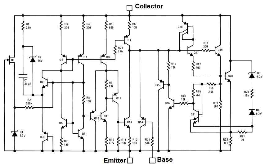
Internal Schematic
The following diagram shows the complex internal schematic of the M195/LM393 power transistors which provide the transistors with enhanced power handling capabilities.
Application Circuits
The following paragraphs explain a few interesting application circuit using the power transistors LM195 or LM393. The most crucial features of these circuits that the power transistors are virtually indestructible.
1 Amp Voltage Follower
The following circuit shows how the device LM195 can be applied as a power voltage follower circuit:
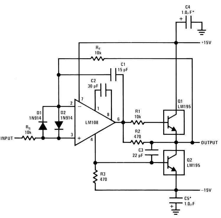
In this circuit when an extremely low current voltage is applied across the input of the circuit, it is replicated at the output with at least 1 amp current. Since the output voltage follows the input voltage supply, it is called a voltage follower.
Simple Lamp Flasher
The LM195 or LM393 devices can be used to configure a simple automatic lamp flasher circuit as shown in the following diagram.
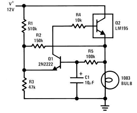
The circuit is able to switch 12 V lamps with upto 1 amp current. The flashing rate can be adjusted by altering the values of R5, C1.
PNP Power Transistor
You can easily convert an LM195 or a LM393 into a PNP power transistor as shown in the following diagram:
R1 protect the configuration against over current while 500 pF capacitor provides proper stability to the circuit and prevents the circuit from oscillating. The maximum current handling capacity of this PNP transistor is 1 amp.
Simple Delay OFF Timer
The LM195 or LM393 can be configured into a simple delay OFF timer circuit as shown in the following diagram:
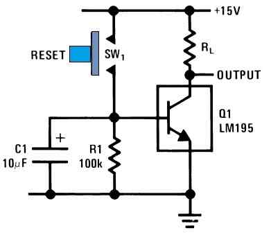
When the push button is push and released, the 10 uF charges and switches ON the LM195 transistors causing its collector load to switch ON. After this, the 10 uF capacitor slowly begins discharging through the 100K resistor until its charge becomes too low to hold the transistor ON.
The LM195 now switches OFF and remains switched OFF until the push button is yet again push and released.
The delay OFF time can be significantly increased by increasing the values of C1 and R1.
High Frequency Oscillator
If you are looking to build a highly accurate, high frequency oscillator circuit which can handle upto 1 amp current, then this design might help.
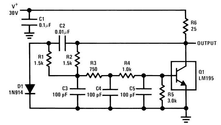
The circuit is designed to generate a very high output frequency of 1 MHz using a single LM195 power transistor. Since the device LM195 can handle upto 1 amp current, this 1 MHz oscillator could be used to switch loads upto 1 amp, with 1 MHz frequency.
Switching Regulator Circuit
The LM195 and LM393 devices can be also used to build high quality switching regulator circuit as given in the following diagram:
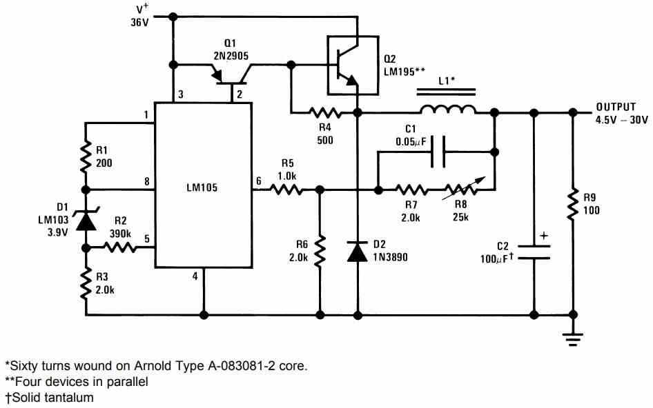
The best feature of this type of switching regulator is that it works with high efficiency and with minimum dissipation. Meaning, these regulators will convert a high voltage input into a low voltage output without generating a lot of heat.
For example, in the above diagram imagine the input is 36 V 100 mA, and we want to convert this into a 5 V output. Then the output will try to retain the input power as much as possible by dissipating minimum heat from the transistor.
Input power will be 36 x 0.1 = 3.6 watts, so the output current would be around 3.6 / 5 = 0.72 amps at 5 V.
Here we can see that the reduction of voltage from 36 V to 5 V results in an increase in current from 100 mA to 720 mA.
For more technical details you can refer to the following datasheet of the device.


Need Help? Please Leave a Comment! We value your input—Kindly keep it relevant to the above topic!