In this post I have explained how to build a letter box open indicator circuit, which indicates through an LED if the letter box had been opened either by the postman, or by somebody else!
The idea was requested by Mr. Bill.
I wonder if you could help me.
I want to make an LED indicator to show whenever my mailbox has been opened.
What I have in mind is a simple battery circuit with a microswitch in the letterbox that triggers the LED and reset button on the outside. This should be easy but I’m not sure how I can make the LED stay on until I push the reset button?
Any advice or pointing to an existing product would be very helpful.
Letter Box Set up
The following figure shows the set up configuration of the letter box, in which the various electronic units and their placements are depicted.
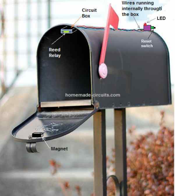
In this set up we have used a reed switch and magnet arrangement for switching the circuit instead of a micro-switch, for ensuring higher working efficiency, and minimum wear and tear of the system. Nevertheless, if a microswitvh is preferred, the reed switch could be simply replaced with a microswitch for getting the same operational features.
The magnet can be seen glued to the inner top edge of the letter box lid, while the reed relay is positioned at the top inside portion of the letter box, in such a way that when the lid is closed the magnet comes face to face and at a close proximity to the reed relay.
The reed relay terminals are configured with an electronic latch circuit which includes an LED for the indicating an opened letter box situation.
When the lid of the letter box is closed and the reset button pressed, the magnet keeps the reed relay contacts closed and the circuit goes into a standby mode. The LED remains shut off in this situation.
Now, if the lid of the letter box is opened, the reed relay contacts release, causing the connected circuit to latch up, and the LED illuminates. In this position even if the lid is closed again, the LED continues to be in the switched ON condition, indicating the owner regarding an previously opened letter box.
The LED can be shut off only by pressing the reset button, with the letter box lid in the closed position
How the Circuit Works
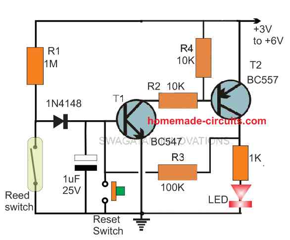
The following figure shows the part configuration for making the letter box open indicator circuit. The design is basically a transistor latch circuit using a couple of transistors with a feedback loop for the latching.
The working procedure of the circuit could be understood with the following points:
Basically, since it is a latch circuit, the circuit will switch ON the LED and get latched as soon as power is switches ON.
When power is switched ON, the transistor T1 is triggered ON through R1, which switches ON T2, and the entire system gets latched via the feedback resistor R3.
In this situation, even if the R1 connection is removed, the transistor would still remain latched and the LED will continue to remain illuminated.
For our letter box open indicator application we want the LED to be switched OFF while the lid of the box is in the closed position, and once it is opened only then the LED should go into a permanently ON position regardless of whether the lid is closed back or not.
For this, we have employed a reed switch, or reed relay whose contacts remain open in the absence of a magnetic field and the contacts close when a magnet is brought near the reed switch device.
As depicted in the previous letter box figure, the circuit is initiated by keeping the lid of the letter box closed, which causes the magnet to reach very near to the reed switch so that its contacts now close.
Next, power is switched ON to the circuit.
However, in this situation the latch is unable to operate because the reed switch contacts ground the base of T1. If T1 cannot switch ON, T2 also cannot switch ON, and the entire latching system remains deactivated.
Now, if the letter box is opened, the magnet is pulled away from the reed relay, causing its contacts to open.
When the reed switch contacts open, it removes the grounding of the R1 base current, enabling the switching ON of transistors T1, T2, and the entire system latches ON via R3.
The LED now illuminates indicating that the letter box had been opened by somebody.
In this situation, even if the letter box lid is closed, causing the reed relay contacts to close, and R1 current to become zero, that does not break the latch, since the T1 base keeps getting the biasing current via R3.
The LED now turns permanently ON, until the owner of the letter box presses the hidden reset switch.
The reset switch grounds the feedback latching current via R3 and cuts off the supply to T1 base which ultimately breaks the latch, switching OFF the LED.
However, this resetting must be done with the letter box lid in the closed position (reed relay closed and grounded). The resetting function will not work if the lid of the letter box is in the open position.
Using a Microswitch
If you prefer using a microswitch instead of the reed relay, you can simply replace the reed relay with the terminals of the microswitch for enabling the same operations, as discussed in the above paragraphs.
In this case, the magnet will not be required, and the micro-switch can be positioned in such a way that when the lid of the letter box is closed, it presses the micro-switch into a switched ON condition.

Comments
Hi Swagatam, I was just reading through your “Letterbox Open Indicator Circuit” project and I noticed a small error in your description of the ‘Circuit Operation’ where you have said:
…..”However, this resetting must be done with the letter box lid in the closed position (reed relay open). The resetting function will not work if the lid of the letter box is in the open position.”
IN FACT, when the letterbox lid is Closed, and hence the Reed-Relay is then magnetically-coupled to it by its close proximity to the Magnet mounted on the Lid, the Relay contact is at that point, Actually, CLOSED, NOT, Open, as is currently, incorrectly described in your Circuit Operation description.
The CLOSED Relay contact of course Grounds, and Holds-Grounded, (until the Lid is opened again) the Anode end of the 1N4148 Diode hence preventing T1, and thus, T2, from turning on again, after, the Capacitor has been discharged, by the operation of the Reset-Switch, and the Reset Button has then, been Released.
Regards,
AOF
23Jun2025
Thanks AOF, you are correct, I have now corrected the typo, and now it seems to be making proper sense.
Thanks again for point out the error…
Hello, is the reset switch implied here pushbutton switch?
yes, it is a momentary push-to-ON switch.
Hello, do you have PCB Layout for this? I’m trying a new project. Thanks!
I am Sorry, I do not have a PCB layout for this project.
Swagatam, I like this idea and interested in developing it further by adding a RF transmitter and receiver. I have only put to together a few same electronic projects many years ago, but I feel I could build something with your assistance. Please let me know if you would be up to the challenge.
Hello Bill, sure, if you can specify your requirement, I will try to figure it out!
Will a 9v battery work okay with this circuit as is or do resistor values need to be slightly increased?
yes 9V can be used without any changes in the existing diagram…
Thanks, the circuit works great with a 9v battery. However I switched to a battery eliminator wall adapter so I don’t need to be concerned about how long the battery would last. I do have an issue of the circuit falsely triggering intermittently when my low voltage house light switches in the area are used and relays activated for my garage & breezeway lighting. This is not the fault of your circuit but, do you have any ideas to shield this from happening?
Glad it is working for you. The issue you have mentioned must not arise since there’s a 1uF capacitor positioned at the base of the BC547 transistor, which is supposed to absorb all the ambient disturbances.
Try increasing its value to 33uF/25V or 4uF/25V and check whether it solves the problem or not. You can also connect the emitter of BC547 through a 1N4148 diode to ground.
Hi Swagatam,
Success!
My fault, I had mixed up R1 (1m) and R3 (100k), so of course it wouldn’t work 🙂
All sorted now and works perfectly.
That’s great Bill, glad you could finally make it work, thanks for the update!
Hi Mr Swagatam,
Unfortunately my first attempt hasn’t worked! (but I enjoyed making it :-)). It’s probably something that I’ve done wrong so I’m faultfinding now.
Quick question, does the 1uf capacitor need to be 25v or can it be 100v? The only 1uf 25v I could find is a very small tantalium capacitor and it think it needs to be a bigger electrolytic?
Many thanks
Bill
Hi Bill, the circuit is pretty straightforward and should work without any problems. For testing purpose you can replace the reed switch with a push button. When you switch ON power the LED will light up and will not switch OFF even if the push button is pressed. This will indicate that the latch system is working. Next, keep the push button pressed and then push the reset button, this will switch OFF the LED and keep it switched OFF as long as the push button (reed switch) remains switched ON. This will indicate that the reed relay points are working too.
The voltage of the capacitor just needs to be well above the supply DC input, that’s all. Tantalum should also work without any issues.
Hi Mr Swagatam,
Thanks very much for this, you are very kind 🙂
I will order the parts and put it together next week and I will keep looking at your website as you have some really useful ideas on here.
Best regards
Mr Bill
Thank you Bill, It is my pleasure!
I have tried to design it as per your suggestions, I hope it works for you.
Let me know if you any problems with the circuit.