In this post we are going take a look at “I2C” or “IIC” or “I square C” based LCD adapter module, which will reduce wire connections between Arduino and LCD display to just 2 wires, also saving tons of GPIO pins for other sensors / drives etc.
Before I have explained about I2C LCD adapter module, it is important to understand what I2C bus is and how it works.
But anyway you don't need to be an expert with I2C protocol to work with this mention LCD adapter.
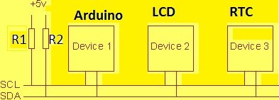
Illustration of I2C connection:
The I2C or IIC stands for “Inter-Integrated Circuit” is a serial computer bus invented by Philips semiconductors, today known as NXP semiconductors. This bus system was invented in 1982.
What is Bus?
Bus is a group of cables / wires which carry data from one chip to another chip / one circuit board to another circuit board.
The main advantage of I2C bus protocol is that, the supported microcontroller or sensors or chips can be interlinked with just two wires. The mind blowing advantage of this protocol is that, we can interconnect 127 different chips or sensors / drivers to one master device which usually a microcontroller with just 2 wires.
What are the two I2C wires?
The two wires are SDA and SCL which are Serial Data and Serial clock respectively.
The Serial clock or SCL is used to sync the data communication over I2C bus. The SDA or Serial Data is the data line in which the actual data is conveyed from master to slave and vice versa. The master device controls the Serial clock and decides for which slave device it needs to communicate. No slave device can initiate a communication first, only master device can do.
The Serial data line is bidirectional and robust, after every set of 8 bit data is send, the receiving device sends back an acknowledgement bit.
How fast I2C protocol is?
The original version of I2C protocol developed in 1982 supported 100 Kbps. The next version was standardized in 1992 which supported 400Kbps (Fast mode) and supported up to 1008 devices. The next version was developed in 1998 with 3.4 Mbps (High speed mode).
Several other I2C versions were developed in the years 2000, 2007, 2012 (with 5Mbps Ultra-Fast mode) and the recent version of I2C was developed in 2014.
Why pull-up resistors in I2C bus?
The SDA and SCL are “open-drain” which means both the lines can go LOW but it can’t drive the lines HIGH, so a pull-up resistor is connected on each of the lines.
But with most of the I2C modules such as LCD or RTC has built in pull up resistors, so we no need to connect one unless it is specified.
Pull-up / Pull-down resistor: Pull-up resistor is a resistor connected to +Ve line of the supply to keep the logic level of a line to HIGH if the line is neither high nor low.
A pull-down resistor is a resistor connected to –Ve line of the supply to keep the logic level of a line to LOW if the line is neither high nor low.
This also prevents noise entering the lines.
We hope we scratched the surface of I2C protocol, if you need more information on I2C protocol, please surf on
YouTube and Google.
Now let’s take a look at the I2C LCD module:
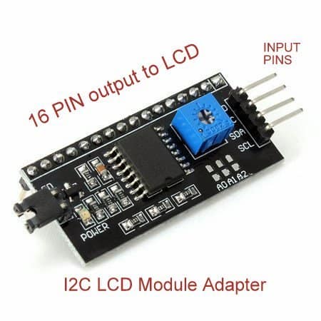
There are 16 output pins for LCD display which can be soldered directly to back of the 16 X 2 LCD module.
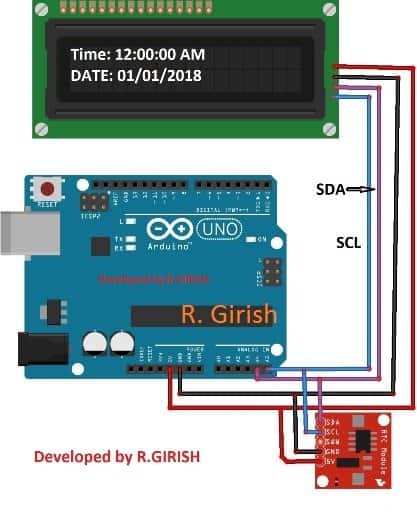
The input pins are +5V, GND, SDA and SCL. The SDA and SCL pins on Arduino Uno are pins A4 and A5 respectively. For Arduino mega SDA is pin #20 and SCL is pin #21.
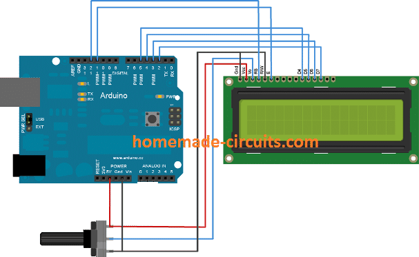
Let us compare how it looks when we wire up the LCD to Arduino without the I2C adapter and with the adapter.
Without I2C Adapter:
With I2C adapter:
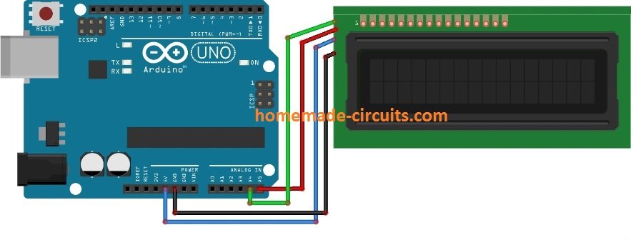
The Adapter is soldered on the back of the LCD display and as we can see that we saved loads of GPIO pins for other tasks and also we can continue add 126 more I2C devices to pins A4 and A5.
Please note that the standard Liquid Crystal library won’t work with this I2C LCD adapter, there is a special library for this, which will be covered soon and we’ll show you how to use this module with coding example.
How to Connect I2C Adapter to 16 x 2 Display
In the above sections of the article I have explained the basics of I2C protocol and took a basic overview on I2C LCD adapter module. In this post I have explained how to connect the I2C LCD adapter module to 16 x 2 LCD display and we will see how program with an example.
The major advantage of I2C protocol is that we can wire the supported sensors / input / output devices in just two lines and it is helpful with Arduino as it has limited GPIO pins.
Now let’s see how to connect the module to LCD.
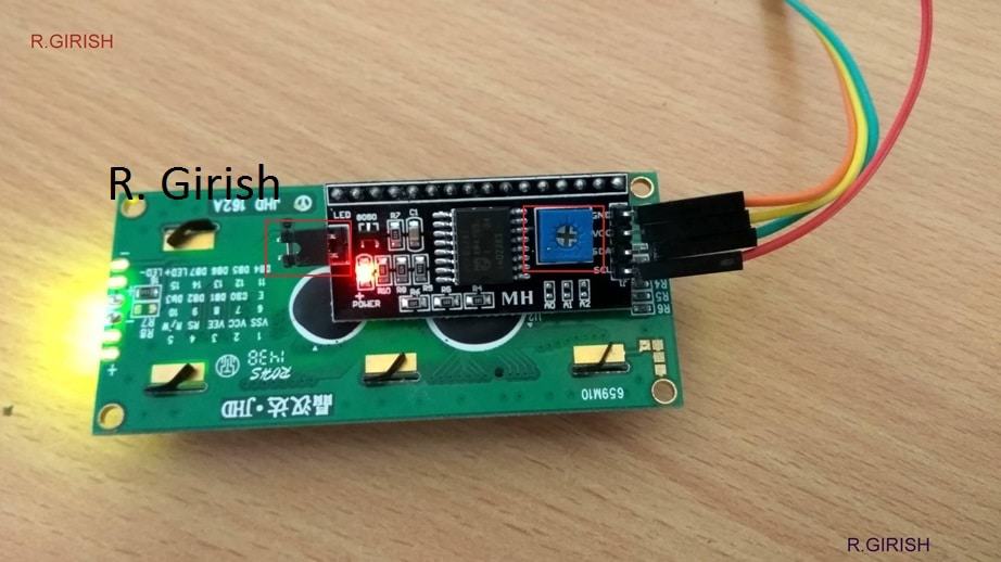
The module has 16 output pins and 4 input pins. We can just solder the adapter to the back of the 16 x 2 LCD display. Out of the 4 input pins, the two are +5V and GND, rest of the two are SDA and SCL.
We can see that we saved a lot of pins at Arduino for other input / output tasks.
We can adjust the contrast of the display by adjusting the potentiometer with small screw driver (highlighted in red box).
The backlighting now can be controlled in the program code itself:
lcd.backlight();
This will turn ON the backlight on the LCD display.
lcd.noBacklight();
This will turn OFF the backlight on the LCD display.
We can see there is a jumper connected, which is highlighted in red box, if the jumper is removed the backlight remains OFF regardless of the program command.
Now the hardware setup is done, now let’s see how to code. Please remember that I2C LCD module needs special
library and the pre-installed “liquidcrystal” library won’t work.
You can download the I2C LCD library from here and add to Arduino IDE:
github.com/marcoschwartz/LiquidCrystal_I2C
From the previous post I explained that I2C devices have address by which the master or the microcontroller can identify the device and communicate.
In most case, for the I2C LCD module the address would be “0x27”. But different manufacture may have different address. We have to enter the correct address in the program only then your LCD display will function.
To find the address just connect 5V to Vcc and GND to GND of Arduino and SCL pin of I2C module to A5 and SDA to A4 and upload the below code.
This will scan the connected I2C devices and show their address.
// -------------------------------- //
// Improved I2C Scanner
#include <Wire.h>

void setup() {
  Wire.begin();
  Serial.begin(9600);
  while (!Serial);

  Serial.println(F("-----------------------"));
  Serial.println(F("   I2C Device Scanner   "));
  Serial.println(F("-----------------------"));
}

void loop() {
  uint8_t error, address;
  int devices = 0;

  Serial.println(F("\nScanning I2C bus..."));

  for (address = 1; address < 127; address++) {
    Wire.beginTransmission(address);
    error = Wire.endTransmission();

    if (error == 0) {
      Serial.print(F("Device found at 0x"));
      if (address < 16) Serial.print("0");
      Serial.print(address, HEX);
      Serial.println(F(" ✔"));
      devices++;
    }
    else if (error == 4) {
      Serial.print(F("Unknown error at 0x"));
      if (address < 16) Serial.print("0");
      Serial.println(address, HEX);
    }

    delay(2); // short delay for bus stability
  }

  if (devices == 0) {
    Serial.println(F("No I2C devices found."));
  } else {
    Serial.print(F("Scan complete. Devices found: "));
    Serial.println(devices);
  }

  Serial.println(F("-----------------------"));
  delay(5000);
}
// -------------------------------- //
Upload the code and open the serial monitor.
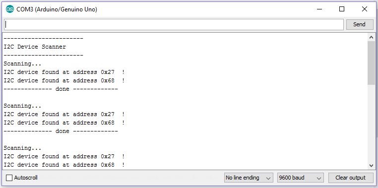
As we can see two devices were detected and their addresses are displayed, but if you want to find only the address of the I2C LCD module, you should not connect any other I2C devices while scanning.
So in conclusion we got the address “0x27”.
Now we are going to make a digital watch as example because there are two I2C devices, the LCD module and RTC or real time clock module. The both modules will be connected with two wires.
Download the following library:
RTC library: github.com/PaulStoffregen/DS1307RTC
TimeLib.h: github.com/PaulStoffregen/Time
How to set time to RTC
• Open Arduino IDE and navigate to File > Example > DS1307RTC > set time.
• Upload the code with completed hardware and open serial monitor and you are done.
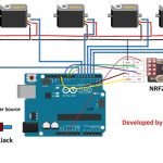
Circuit diagram:
Program:
#include <Wire.h>
#include <LiquidCrystal_I2C.h>
#include <TimeLib.h>
#include <DS1307RTC.h>

LiquidCrystal_I2C lcd(0x27, 16, 2);

void setup() {
  lcd.init();
  lcd.backlight();
}

void loop() {
  tmElements_t tm;
  lcd.clear();

  if (RTC.read(tm)) {
    // AM/PM
    bool isPM = (tm.Hour >= 12);

    lcd.setCursor(0, 0);
    lcd.print("TIME: ");

    // Convert to 12-hour format
    int displayHour = tm.Hour % 12;
    if (displayHour == 0) displayHour = 12; // 12 AM or 12 PM

    // Print time with leading zeros
    if (displayHour < 10) lcd.print("0");
    lcd.print(displayHour);
    lcd.print(":");
    if (tm.Minute < 10) lcd.print("0");
    lcd.print(tm.Minute);
    lcd.print(":");
    if (tm.Second < 10) lcd.print("0");
    lcd.print(tm.Second);

    // Print AM/PM
    lcd.setCursor(14, 0);
    lcd.print(isPM ? "PM" : "AM");

    // Print date
    lcd.setCursor(0, 1);
    lcd.print("DATE: ");
    if (tm.Day < 10) lcd.print("0");
    lcd.print(tm.Day);
    lcd.print("/");
    if (tm.Month < 10) lcd.print("0");
    lcd.print(tm.Month);
    lcd.print("/");
    lcd.print(tmYearToCalendar(tm.Year));

  } else {
    // Error handling
    lcd.setCursor(0, 0);
    if (RTC.chipPresent()) {
      lcd.print("RTC stopped!!!");
      lcd.setCursor(0, 1);
      lcd.print("Run SetTime code");
    } else {
      lcd.print("Read error!");
      lcd.setCursor(0, 1);
      lcd.print("Check circuitry!");
    }
  }

  delay(1000);
}
Note:
LiquidCrystal_I2C lcd(0x27, 16, 2);
The “0x27” is the address which we found by scanning and 16 and 2 are the number of rows and columns on the LCD display.
For RTC we no need to find the address but we did find while scanning “0x68”, but anyway the RTC library will handle it.
Now let’s see how much we reduced the wire congestion and saved GPIO pins on Arduino.
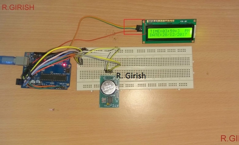
Only 4 wires are connected to the LCD display, highlighted in red box.
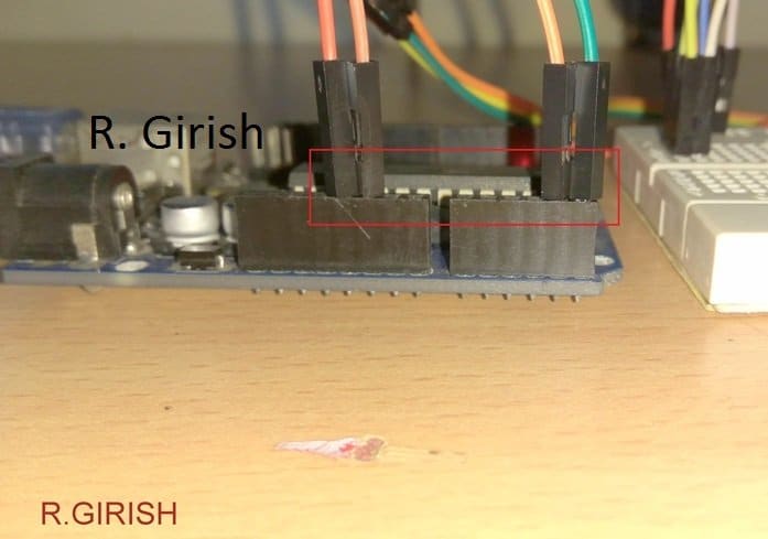
Also only 4 wires are connected from Arduino and the RTC module shares the same lines.
By now you have gained basic knowledge on I2C and how to use the I2C LCD adapter module.
Do you like this post? Do you have any questions? Please express in the comment section, you may get a quick reply.

Comments
hi swag,
i need a big help about multitasking program in arduino.
for instant i have an ultrasonic sensor which measure instantly and operate, hold a 5v relay in particular distance with some time delay, at the same time i want to measure temperature and humidity and it report lcd display from begining, and a led instantly blink.
please brief me how its possible. arduino
Hi Abdul,
I am sorry, customized codes for Arduino is a premium offer, presently we are quoting Rs.10/- for each line of custom code.
If you are interested please let us know we’ll arrange the procedures.
Great explanation. Thank you.
Glad you liked it!!