This article discusses a method through which any ready made SMPS can be converted into a variable current smps circuit using a few external jumper links.
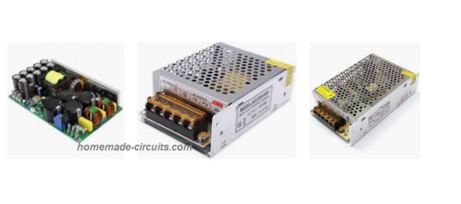
In one of the previous articles I have explained how to make a variable voltage SMPS circuit by employing a simple shunt regulators stage, in the present hack also we employ the same circuit stage for implementing a variable current output feature.
What is SMPS
SMPS stands for Switch-Mode-Power-Supply, which uses a high frequency ferrite based switching converter for converting the AC 220V to DC. The use of a high frequency ferrite transformer makes the system highly efficient in terms of compactness, power loss, and cost.
The SMPS concept today has almost completely replaced the traditional iron core transformers and have transformed these units into a much compact, light weight and efficient power adaptor alternatives.
However since SMPS units are commonly available as fixed voltage modules achieving a preferred voltage as per the users application needs becomes quite difficult.
For example for charging a 12V battery one may need an output voltage of around 14.5V, but this value being quite odd and non-standard we may find it extremely difficult to get an SMPS rated with these specs in the market.
Although variable SMPS circuits can be found in the market, these may be costlier than the ordinary fixed voltage variants, therefore finding a method of transforming an existing fixed voltage SMPS into a variable type looks more interesting and desirable.
By investigating the concept a little I was able to find a very simple method of implementing the same, I have explained how to conduct this modification.
You will find one popular 12V 1amp SMPS circuit in my blog which actually has an in built variable voltage feature.
The Function of Opto-coupler in SMPS
In the above linked post I have explained how an opto coupler played an important role in providing the crucial constant output feature for any SMPS.
The function of the opto coupler may be understood with the following brief explanation:
The opto coupler possesses an inbuilt LED/photo-transistor circuitry, this device is integrated with the SMPS outputs stage such that when the output tends to rise above the unsafe threshold, the LED inside the opto lights up forcing the phototransistor to conduct.
The photo-transistor in turn is configured across a sensitive "shut down" point of the SMPS driver stage wherein the conduction of the photo-transistor forces the input stage to shut down.
The above condition results in the SMPS output to also instantaneously shut down, however the moment this switching initiates, it corrects and restores the output to the safe zone and the LED inside the opto deactivates which once again switches ON the input stage of the SMPS.
This operation keeps on cycling rapidly from On to OFF and vice versa ensuring a constant voltage at the output.
Adjustable Current SMPS Modification
In order to achieve a current control feature inside any SMPS we yet again seek the help of the opto coupler.
We implement a simple modification using a BC547 transistor configuration as shown below:
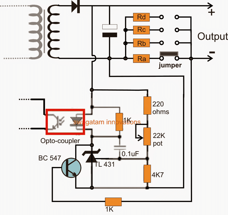
Referring to the above design we get a clear idea regarding how to modify or make a variable current SMPS driver circuit.
The opto coupler (indicated by red square) will be present by default for all SMPS modules, and assuming that the TL431 is not present then we may have to configure the entire configuration associated with opto coupler LED.
If the TL431 stage is already a part of the SMPS circuit, in that case we just have to consider integrating the BC547 stage which becomes solely responsible for the proposed current control of the circuit.
The BC547 can be seen connected with its collector/emitter across the TL431 IC's cathode/anode, and the base of BC547 can be seen connected with the output (-) of the SMPS via a group of selectable resistors Ra, Rb, Rc, Rd.
These resistors being in between the base and emitter of the BC547 transistor begin functioning like current sensors for the circuit.
These are appropriately calculated such that by shifting the jumper connection across the relevant contacts, different current limits are introduced in the line.
When the current tends to increase beyond the set threshold as determined by the values of the corresponding resistors, a potential difference is developed across the base/emitter of the BC547 which becomes sufficient to turn ON the transistor, shorting the TL431 IC between the opto LEd and ground.
The above action instantly lights up the LED of the opto, sending a "fault" signal to the input side of the SMPS via the opto's in-built photo transistor.
The condition immediately tries to execute a shut down across the output side which in turn stops the BC547 from conducting and the situation fluctuates from ON to OFF and ON rapidly ensuring that the current never exceeds the predetermined threshold.
The resistors Ra...Rd may be calculated by using the following formula:
R = 0.7/cut-of current threshold
For example if suppose we want to connect an LED at the output having a current rating of 1 amp.
We can set the value of the corresponding resistor (selected by the jumper) as:
R = 0.7/1 = 0.7 ohm
Wattage of the resistor can be simply gotten by multiplying the variants, i.e. 0.7 x 1 = 0.7 watts or simply 1 watt.
The calculated resistor ensures that the output current to the LED never crosses the 1 amp mark, thereby safeguarding the LED from damage, other values for the remaining resistors may be appropriately calculated for getting the desired variable current option in the SMPS module.
Modifying a Fixed SMPS into Variable Voltage SMPS
This following post tries to determine a method through which any SMPS could be made into a variable power supply for achieving any desired voltage level from 0 to maximum.
What is Shunt Regulator
We find that it employs a shunt regulator circuit stage for executing the variable voltage feature in the design.
Another interesting aspect is that this shunt regulator device implements the feature by regulating the input of the opto coupler of the circuit.
Now since a feedback opto coupler stage is invariably employed in all SMPS circuits, by introducing a shunt regulator one can easily transform a fixed SMPS into a variable counterpart.
In fact one can also make a variable SMPS circuit using the same principle as explained above.
You may want to learn more about what's a shunt regulator and how it works.
Procedures:
Referring to the following example circuit, we are able to find the exact location of the shunt regulator and its configuration details:
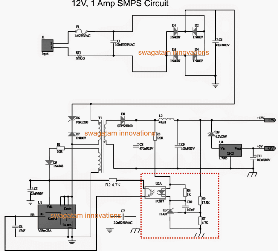
See the bottom right side of the diagram marked with red dotted lines, it shows the variable section of the circuit we are interested in. This section becomes responsible for the intended voltage regulation actions.
Here the resistor R6 can be replaced with a 22K pot for making the design variable.
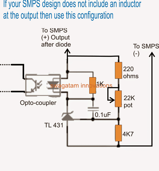
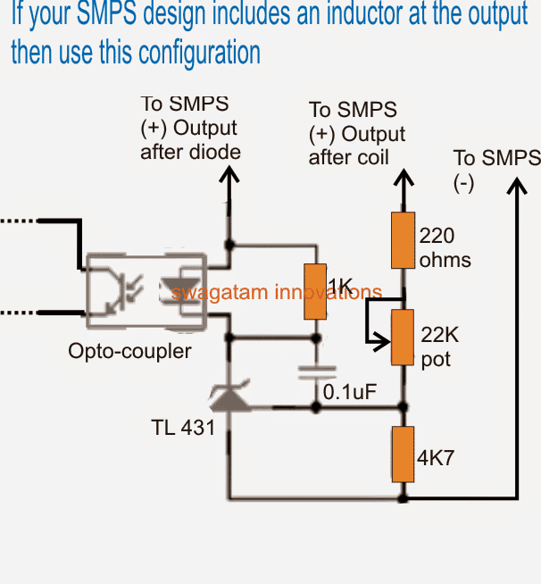
Magnifying this section provides a better view of the involved details:
Identifying the Optocoupler
If you have a fixed voltage SMPS circuit, open it and just look out for the optocoupler in the design, it would be mostly located just around the central ferrite transformer, as may be seen in the following image:
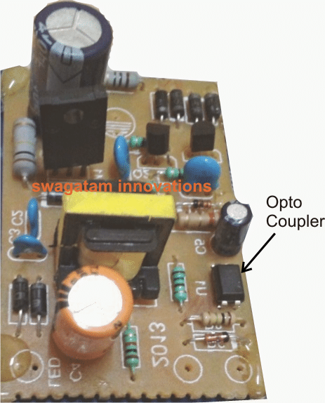
Once you have found the opto-coupler, clean up by removing all the parts associated on the output side of of the opto, meaning across the pins which may be towards the output side of the SMPS PCB.
And connect or integrate these pins of the opto with the assembled circuit using the TL431, shown in the previous diagram.
You can assemble the TL431 section on a small piece of general purpose PCB and glue it on the main SMPS board.
If your SMPS circuit does not have an output filter coil, you can simply short the two positives of the TL431 circuit and join the termination to the cathode of the SMPS output diode.
However suppose your SMPS already includes the TL431 circuit with the opto coupler then simply find the position of the R6 resistor and replace it with a pot (see R6 location in the first diagram above).
Don't forget to add a 220 ohms or 470 ohm resistor in series with the POT otherwise while adjusting the pot to the upper most level could instantly damage the TL431 shunt device.
That's it, now you know exactly how to convert or make a variable voltage SMPS circuit using the above explained steps.
Warning: SMPS circuits are not isolated from AC Mains on the primary side, and can be lethal to touch while in uncovered and switched ON condition.
UPDATE
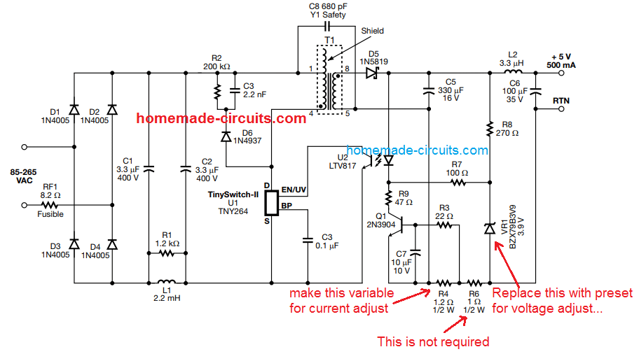
The following image shows perhaps the easiest way to customize an SMPS circuit for getting a variable voltage and current features. Please see how the pots or presets needs to be configured across the opto-coupler for getting the intended results:
If you have any further doubts regarding the design or the explanation, feel free to express through your comments.
Let's Summarize
In this write up we quickly try to summarize the main points regarding how to modify any SMPS circuit through an easy hack which may help us to get a desired customized output from the unit.
What is an SMPS
SMPS stands for switch mode power supply and it's the modern and most compact/efficient way of acquiring low voltage DC from mains AC source.
However making an SMPS at home may not be as simple as making power supply units using traditional iron core transformers.
Also getting an SMPS with custom specs may not be that easy, in fact impossible if the voltage/current specs are far away from the regular values.
So does that mean we have to be satisfied with the SMPS specs which are typically set, and available in the market?
For example how do we find an SMPS having an output of say 13 volts or 14 volts or 17 volts which are definitely not the normally accepted voltage ranges?
Customizing an SMPS unit
Since making such a customized unit may not be an easy task (due to complex layouts and part configurations) it would be a lot better if we could find ways of modifying a readymade one through some simple steps.
I have studied a few standard SMPS units and hopefully cracked ways of modifying the voltages and current as per individual choices. I have explained it in details.
When you open any standard SMPS unit, you will come across the following things over the enclosed assembled card.
The populated PCB can be primarily divided into two sections by the presence of the center ferrite transformer.
The side of the transformer where the mains chord makes its entry is the input AC section while the other side from where the low voltage DC is derived is the DC section.
We are not interested in the AC section because we do not want to modify the input voltage so do not pay any attention there, moreover the AC section is POTENTIALLY VERY DANGEROUS TO TOUCH IN SWITCHED ON CONDITION, THEREFORE KEEPS YOUR HANDS OF IT WHILE TESTING.
The DC section will mainly consist of a couple of chokes, a couple of filter capacitors, a diode and a few other components.
Look for the Shunt Regulator
Search for a transistor shaped component in this section. If you find a couple of them, one will be actually a transistor, probably for limiting the output current, however the other one will be definitely THE PROGRAMMABLE SHUNT REGULATOR.
This shunt regulator is the component which fixes the feedback voltage to the AC section mosfet and in turn determines the output voltage.
This programmable shunt device is set up through a couple of resistors, changing which will instantly change the output voltage as per ones wish.
Try to locate the resistors connected with the leads of this shunt device. One of them can be simply varied for changing the output voltage as per your preferences.
Take an external resistor of any value may be a 4k7 1/4 watt, now step-wise go on connecting this resistor across the resistors which are associated with the shunt regulator device.
Check and Verify the Output
Verify the output voltage each time you do the above step.
The moment you find a change in the output voltage either becoming low or high, you might have just found the one which we are looking for.
Now through some trial and error you may find out the exact value of resistor which could be replaced in place of the particular shunt resistor.
That's it, it's as simple as that, once you do it, the output voltage would get adjusted to that particular value permanently.
But do remember to remove the zener diode if there's any at the output of the power supply before you do the above procedures.


Questions & Answers
Sir, I have made this circuit and connected to TNY268 based smps( output voltage=35 volt ). But I could not adjust the output voltage by varying 22k pot. In my circuit, I have connected Ra=1 ohms but I could not get 0.7 volt across base-emitter of BC547. Please help.
Arindam, try adjusting the 4k7 and check the response.
remove the BC547 and now check the voltage across Ra… confirm at what load the 0.7V is achieved across Ra…once this is confirmed you can reconnect the BC547 connections with Ra and check the response again by applying the same load….
How much max current can handle? 10A/50A/???
Sir ,what causes voltage drop in smps under load ,after one year of 24×7 use in the same 1 .5 amp load but after a year the adaptor voltage dropping ,i check the volt it’s showing 5.4 volt it’s ok but under load it’s vot dropping in to 2.1 vot , i replaced all caps first stage and second stage and o/p diode also replaced but not working ???? can u plz suggest any idea ,and also I research in Google about voltage drop isssu but I can’t find anything ,plz reply ????
Hi Vyshak, in any power supply system the voltage will drop if the source is unable to provide sufficient current, which can happen if the power handling device or the transformer is defective. Or perhaps the feedback system can be also defective, which may be shutting down the primary due to an incorrect current sensing.
You can first remove the feedback link, and the check the output with a load. If that doesn’t solve the issue, next you could try replacing the power mosfet or the power IC with a new one. One of these will be responsible for the fault and you could finally resolve the issue through these steps, hopefully.
Thanks for reply ,i will check and updated u????
depends on how the smps is built…
Dear Sir, thank you very much indeed for the above circuits!
I’ve also seen https://makingcircuits.com/blog/add-this-adjustable-current-circuit-to-your-power-supply/
However, the idea of having a switch S1 (to choose between P3, P2) does not appeal to me. Moreover the ICL8069 is obsolete.
I like to modify 24V 10A SMPS to get variable voltage from 0-24V and Current from 500mA-10 Amp.
Can you please help ?
Thank you once again in anticipation
Thank you Imsa, The idea explained in the above article is the only information I presently have, I don’t think there can be any other easier option than the above method. The current resistors could be selected using a rotary switch if the selector switch is not acceptable.
Dear Sir, thank you very much for the express reply, and sorry to bother again…
I beg to once again refer to https://makingcircuits.com/blog/add-this-adjustable-current-circuit-to-your-power-supply/
would there be an alternative to the ICL8069 for the circuit ? or can I request you to kindly modify the circuit using an alternative IC ?
I am very keen to have “Adjustable current output” from the smps.
Thank you very much again.
Dear Imsa, there seems to be no IC2, at least I cannot see it in the diagram, so you can just ignore it.
Its not given in the diagram, but the explanation note it says quote “The switch S1 enables to have 2 working ranges employing a voltage division rate governed by IC2 pretty much significant” unquote, also in the parts list-“IC2: ICL8069”
Now I’m getting confused…..
Would you please help ?
Thanks again.
You can use TL431 instead.
Here’s the article:
https://www.homemade-circuits.com/explaining-programmable-shunt-regulator/
But since it’s not there in the diagram it’s probably a mistake in the content or it might be referring to another design which is not included in the article.
sir thanks for the guidance
i just want to ask that i want to design this circuit on Proteus but i didn’t find any library for integrated power switch so how should i proceed now..
the second question is if we design this model and if so across fet(integrated power switch) there so much heat come so can we reduce this power dissipation by using bc547 transistor across the output stage?
Hi Sam, if it’s not there you will have to add it. You will find many online tutorials which have explained how to add library components.
Yes the BC547 stage or Q1 stage in the last diagram are for limiting current, so they can be configured appropriately for controlling the dissipation.
thanks for the response..i know how to add the library in proteus but the probelm is i have tried alot but still didn’t find libraray file for integrated power switch (fet).can you plz provide me any link or any guidance regarding this
Hi Sam, I am sorry I do not use proteus much so I am not sure about it, I tried searching how to add TNY287 to proteus but it gave no results, so it seems difficult.
ok
Dear Sir, thank you very much indeed for the above update and guidance.
I shall try out the above idea first and get back to you for further guidance.
Thanks again!
Glad to help Imsa, wish you all the best!!
dear sir
I have a quantity of 3.3 v SMPS , How could I modify it to a 24v . thankyou
If you have 10 of these, connect their outputs in series, and the AC inputs in parallel
Hi, thank you, your article helped me to improve the efficiency of a LED lamp, i changed the voltage from 5v to 6.3V , that way i can use 2 LEDs in series and adding just 1ohm resistor.
By the way you forgot to mention that before the modification we must check first the voltage value of the capacitors, the new voltage output could make them explode if overpases that marked value.
Best Regards
Glad it helped, but which capacitor are you referring to?
Hello! You have a very useful website.Thank you to everyone who contributed.I’m waiting for your help with something.I have one smps.The circuit board has an 8-pin pwm controller.Unable to read the name on the pwm controller.I looked through a magnifying glass, but I couldn’t see it.How is the name pwm controller known?
Thanks OLgun, it can be very difficult to trace which 8 pin IC is involved, because there are many types of 8 pin ICs used in SMPS circuits, a few can be found in the following link:
https://www.homemade-circuits.com/?s=smps
I’ll send you a picture of the smps circuit. Can you look at the picture and tell me what the pwm controller is?
Sorry, it can extremely difficult, because there are so many 8 pin SMPS ICs with minor differences in their configurations, so differentiating them can be almost impossible and may take hours.
Hi,
thank you for your article. I try to modify 12V SMPS and set it’s output voltage to 6V, through the resistor connected to Shunt Regulator. I don’t get DC output voltage, but on output I see Sawtooth Waveform with aprox. 6V amplitude.
Thank you.
Hi, was the DC voltage OK before the modification? if it was, then revert it to the previous situation and adjust the preset by keeping the meter connected at the output and check the response…
How did you calculate the resistors value? I would recommend connecting a preset, and do as per the last diagram
Hi,
thank you for the reply.
Before I start to changing the value of resistor, the DC voltage was 12V and the waveform was ok. When I adjusting the value of resistor from 1.2k to the 3.4k (aprox. 6V output), the waveform of output voltage is ok, until I moved to the value 1.9k (8.8V). Within the range 1.9k – 3.4k I always get the sawtooth waveform on output. I used for calculation the formula from datasheet (https://www.diodes.com/assets/Datasheets/AZ431A.pdf) Uout=(1+R1/R2)*Vref.
In schematic of this SMPS is zener-diode placed in the input part (https://ibb.co/StfFCyv).
Hi, The ideal way would be to reduce the secondary winding number of turns and then adjust the R5 value. You can connect a 6 V bulb at the output an see how it responds.
Hi,
I didn’t draw the whole schematic, but only the part with shunt regulator. You mean secondary winding of the high frequency transformer (switching freq. of SMPS is aprox. 23kHz – 55kHz) or secondary winding of low frequency transformer (switching freq. 50Hz)?
Yes, that’s right, the secondary winding of the transformer should be reduced to 50% less number of turns.
Hi,
which transformer? There are two transformers. High frequency and low frequency transformer.
Hi, in SMPS only one transformer is normally used, I was referring to the winding which is being used for getting the 12V output, at J1 in your linked diagram
Hi sir how to make
SMPS , input:230V AC, output:0-100V DC Variable, current 1or 2 or 3amps , output will be shown in digital display, using lab purpose
Hi Mallareddy, 100 V at 2 amp means 200 watts, sorry presently I don’t have an smps circuit with this rating.
May be you can modify the following circuit:
https://www.homemade-circuits.com/smps-2-x-50v-350w-circuit-for-audio/
Hello! Dear Sir,

In the illustration on the connection, there are feedback circuit components of two different atx power supplies.How is this calculated according to the circuit diagram of 2.5V reference voltage?I want to upgrade the + 12v output to 14.4V by making changes to the atx power supply.What should be the resistance values?Would you please let me know?
How is the 2.5v voltage reference for the PowerMan power supply in the picture calculated?
What should be the resistance values when the 12v output voltage of the PowerMan power supply in the picture is increased to 14.4v?
Olgun, please check the following article, you can find a few related formulas that you can apply for your calculations
https://www.homemade-circuits.com/explaining-programmable-shunt-regulator/
Hello,
I have a 55Vcc, 1A SMPS – from ALVARION Israel, with an inductor at the output. I had identifiend the corresponding R6 resistor having 47k.
I have used an 220ohm resitor and a 50k lin pot.
My problem is that the output cannot be adjusted from 0 to 55Vcc. I am only able to get 41-55Vcc.
Yes, it won’t give a linear regulation from 0 from maximum because SMPS working is not linear…the minimum and maximum values will only work for a small range.
Swaga, nice site! I have smps that I am trying to modify for adjustability
It has an unusual feedback reference using the 5v and 12v to
supply the l431 zener. I need help with information on which resistor
to change. I can supply a schematic for your review.
Thank You
Mike
Thanks Michael, I won’t be able to suggest the exact value, it will need to be done with piratical trial and error experimentation.
Thank you for the reply, I am just looking for opinions
as how to proceed not looking for resistor values as
you have posted the calculations on your site for the
math.
The zener gate has been referenced to both 5v and 12v
power supplies in a H bridge configuration. I am looking
for explanations for this type of feedback. (how it works)
Thanks
Mike
The calculations are based on the basic TL431 formulas presented in the following article:
https://www.homemade-circuits.com/explaining-programmable-shunt-regulator/
Hello swag,
I made a smps circuit base on UC3843 and the IRF840 mosfet.
When i pluged in to wall socket the voltage goes high till reaches 27.7v. The circuit does not have feedback system( optocoupler and shunt regulator).
How its voltage will be fixed at some level like 14v? If it is possible with optocoupler &shunt reg., kindly guide me with a circuit?
All i want to know is which pin of UC3843 is used for feedback voltage from optocoupler.
Thanks
Hello Mah, please refer to the second diagram from this article;
https://www.homemade-circuits.com/12v-2-amp-smps-circuit/
The IC is pin to pin compatible with UC3843
good night
Please inform me what the function of the resistor is in parallel with the led of the optocoupler connected to tl 431.
When changing the circuit of a fixed source, to adjustable, it is possible to adjust the maximum voltage from zero to zero, because I changed a 12vdc switched source and managed to change and adjust the voltage from 5.44 to 44vcc
Grateful for the attention
Thanks, the resistor could be for effective triggering of the TL431 IC. No, I don’t think a full zero adjustment may be obtainable from the method which is explained above.
Good Morning
Thanks for the answer
You are welcome
Hello sir,
I was looking to make a transistor based smps with a input range of 180v to 280 v
The smps should not start or stop Below or over respective voltage. Can you help me with circuit. I do not want to use any ic. Smps must be transistor based.
Hello Swapneel, sorry I do not have any schematic or idea for implementing a high/low cut off using an SMPS technology
Ok sir, if u ever do anything like this do upload and share your knowledge with us
Sure thanks!
I have an SMPS charger that pulls out 19v and it has TL431. I don’t want to change the voltage I just want to set a constant current of 1A. Please help me! Thanks!
You can add one of these circuits at the output:
https://www.homemade-circuits.com/universal-high-watt-led-current-limiter/
Thanks for guide.
I have 19 volt 3.7 amp from laptop adapter. If me change the output to 5 volt. With adjust in shunt regulator 431. Can i increase the current in output to many amp at 5 volt ? Without change the secondari winding in transformer ?
Sory for my bad english leanguange thanksss before
Sorry, shunt regulator will not increase current, it will shunt both current and voltage to ground…you will need a buck converter instead
Dear thank you so much for you webpage.
I have a Dell AC adapter.
Model No: LA90PS0-00
PA-10 Family DC 19.5V 4.62A
I would like to turn it to a variable supply power but I cannot find the FEEDBACK RESISTORS to connect the potentiometer. Where to connect the Voltmeter as well?
Your help will be great. I can send the pictures of the opened Dell AC adapter if needed.
Thanks!
Dear Jovin, could you identify the opto-coupler? The opto coupler should be certainly present in your adapter since all standard SMPS adapters usually have this as the feedback controller element.
It can be difficult for me to distinguish the resistors through the image….because the connections can be only verified through a practical inspection.
Please refer to the last diagram, which is a standard format and will match most of the SMPS output feedback configuration with slight variations….
good day sir, i was wondering if i could design an smps topology but with a constant current and variable voltage output instead, current could be either 30, 40 or 50 amps, but even if the circuit doesn’t give the exact output, i just want to see one that will actually achieve a constant currrent, thanks
Hello Odesile, 30-50 amps looks too high, I do not have this design at this moment with me….
Is this circuit going to be OK at 50 v ? I am trying to modify a charger for electric bike battery,
I know that my TL431 have maximum of 36v so I must use voltage divider, but will the BC547 be ok ?
I haven’t figured out yet whether my circuitboard has a zener diode on it, I just know it have an optocoupler
with KA3842 IC, so far I manage to make the output voltage go up but not down.
Yes it can be modified to give 50 V…In place of BC547 you will have to use BC546,,,if zener is not there, there might be a resistor in its place, please check the last diagram and proceed accordingly.
Hello Swagatam!!!
Can me get a 100A at the smps Transformer output whatever the voltage?
Hello Yosh, sorry I do not have this circuit with me presently!
Hello Sir,
Chatali Mistry Here From Baroda.
I Want to make LED Driver as below Specification.
Input Voltage: 70-190V AC/DC, Auto Cutoff T 200-205V
Output Voltage: 24V
Output Wattage : 9 and 18 W
THD: 0.9
Efficiency Should be high.
I have already tried 2 Drivers, in first ATHD and PF is not matching with My required data,
and in another one wattage isn’t reducing below 30w, below 30w it get started flickering.
I have made Matrix of LED of 8Series10Parallel, LED is of 3V,150mA,0.5W.
Kindly Suggest me Driver Circuit According to This.
Thanks.
Hello Chaitali, you can try the following design, however I am not sure about the THD and PF values for this circuit:
https://www.homemade-circuits.com/ceiling-led-lamp-driver-circuit/
For the over voltage auto cut off we will need to add an external relay circuit or a triac cut off circuit
how can calculate the value of inductor(3.3uH) and output capacitor (100uF)….any thumb rule for that plz explain
all the details are in the datasheet at the end of the post….
1. Some Laptop chargers and power supplies don’t use tl431, insted use some ics, may be opamps, pls guide, in those cases if we wish to change its o/p voltage and to change the limit of max o/p current for those cases.
2. Pls suggest the above scenario for power supplies with multiple outputs Like same amps with 12volt and 5volt output at a time.
Thank you in advance.
If TL431 is not used still an opto coupler will be used which will have associated parts like a transistor, zener diode and resistors….you will have to tweak one of those resistors to adjust the output voltage to the desired limits.
I can suggest exactly only if a schematic diagram is available.
For getting multiple outputs you can think about extracting extra tappings from the secondary winding of the SMPS transformer, these tappings can provide with the required levels of output voltages
I have a SMPS of 35v output, uses 431 for feedback, could not make it variable below 28 volts, it uses glass diode at around 431 feedback circuit, old circuit, glass diode couldn’t get read, but lead size and shape looks like a zener, what should I do?
Although it may not be safe to modify the zener without knowing what exactly it is, you can take a chance by replacing it with different resistor values, and check if that alters the output voltage. If it does then you can replace this zener with a preset for getting the desired output.
Hi,
This is A K Gupta, we are looking for 5 nos variable SMPS/ Supply with following specs:
Input : 100-240VAC or only 240VAC would do
Output : 0-26VDC , 6 Amp
Input potentiometer with connector 1.5 mtrs long wire.
Qty : 05 Nos
Please suggest if any one can supply it to us. We are going to use it for powder brake system.
rgds
A K Gupta
Hi, very sorry, we don’t sell SMPS circuits, so we won’t be able to help you with this request!
Thank you
If the main ac voltage fluctuates between 30 volts and 240 volts.
What can I do to make smps psu work especially at that low voltage when AV stabilizer isn’t be helpful?
I don’t think there’s any stabilizer that will boost 30 V to 220 V, so instead you must contact the utility service and lodge a complaint against the problem!
Thanks for prompt response
Is there any smps power supply or circuit diagram that operate correctly from main ac voltage range of 30 volt to 240V?. Ac main voltage often fall as low 30 volt and the available smps power supply will stop working
According to me there’s no SMPS that can work from 30 V to 220 V range. The minimum voltage should be at least 85 V
Hello Swagatam hope you are fine , i have a battery charger for ev 48v battery cutoff at 54.6 ,its based on uc3845 ic and an op amp with shunt resistance for charging control, all is good except the max charging current which goes upto 6.9 amp , i want to limit it to max 6 amp ,can you pls help, it uses tl431 and op amp , voltage is variable but i want to limit max current also ,
thanks and
regards
Hello Sunil, is it an SMPS based charger of transformer based?
As you said in case of smps with VIPER22A, if we operate it in variable voltage configuration what can be the minimum to maximum range of output voltage. Let say I have 12v, 1a smps(with fixed zener) with me, now i want to add variable voltage functionality using tl431 and a pot of 22k,can i get full range control over voltage? from0 to 12v?
I think you can try replacing R7 with a pot in the following diagram, this might provide you a range from 3 V to 12V.
I just bought a dl-psu1800BTC. 12 vdc 150amp psu. Anyone know how to make it variable. Don’t really need it to go lower but I’d like to get it up to 13.8 vdc or 15vdc
Hello, I am a student in the field of industrial electronics in the final year and I need your help in finding a graduation project. I read your article and I did not fully understand it. I want you to suggest to me an electronic circuit through which the voltage and output current can be controlled through a fixed input voltage, or you suggest to me a project that I use for graduation And this will make me very happy. I am in great confusion and time is running out for me. Thank you in advance
Hello, you can try the following concept for building a variable voltage/current regulator. R8, R9 can be used for changing the voltage, and R13 can be used for changing the current
https://www.homemade-circuits.com/5v-pwm-solar-battery-charger-circuit/
I have a new smps 18V 1.8A using one mosfet and 6 pin ic marked 33w9z , when I try adjust output to 8V by 4.7k and pot 10k as divider, it flactuates when output is less than 11v
What is the reason?
Maybe there’s an under-voltage cut off set within the SMPS circuit which is causing the output to go into a continuous switch ON/OFF mode when the voltage is reduced below 11V
Hello, i want to know that if i want to design 12V 2A instead of 12V 1A, what should i do ?
Basically, you may have to change the transformer wire thickness and the mosfet value, if a mosfet is used.
Hello sir,
I’m here again ????
i tried limit current of my smps which is ro smps 36v 4amps with str module insalled on it with proper feedback but when i hookup transistor voltage drops to 15v before adding transistor I’m getting good 42v at output (i did modification to smps to get 42v to charge my lifepo4 12s battery)
I’m getting good amount of current but problem is that current is too much high like 3-4 amps but i want to limit it to 2amps that’s why i tried this circuit i hooked up 6 resistors parallel of 2.2ohms total value I’m getting 0.36 milliohm with bc 547 transistor but voltage drops becomes another problem to me how can i charge my 12s battery with only 15v ????
help me sir
Hello Happie,
Did you check what happens if you remove the base connection of the BC547 from the resistor? If this restores the 42V then the problem could be with the resistor value.
I tried it but no solution i also decreased resistance but facing same issue just removed base of transistor just emitter and C is connected and voltage drops accure.
Then your transistor may be faulty, without base connected the transistor will not conduct and cannot have any effect.
Transistor is new i tested it before connecting ????
Do you have any other method to control current using mosfet or op-amp ?
If your transistor is conducting without a base bias, then it is magic 🙂
The other way is to add a power transistor based circuit at the output, such as this:
R2 and T3 will control the current.
Hehe sorry I’ll try this circuit too ????
BUT calculation ????