A step down transformer is a device which reduces a higher AC potential to a lower AC potential as per its winding ratio and specifications.
In this article we are going to discuss how to design and construct a basic step down transformer which are typically applied in mains-operated power supplies.
Introduction
This will likely help electronic hobbyists to develop and build their very own transformers based on their particular demands.
Within the next pages, a simplified layout method is presented in order to achieve satisfactorily developed transformers. On the other hand, the design process may be a subject of some experimentation.
The tables I have I have explained in this article trim computations short which help the designer to find the appropriate size of wire or even core lamination.
Exclusively pertinent data and calculations are supplied here to ensure that the designer is absolutely not baffled by unwanted details.
Here we will specifically discuss about transformers which possesses 2 or more winding of insulated copper wire around an iron core. These are: one primary winding and one or maybe more secondary winding.
Each winding is electrically isolated from the other however are magnetically connected by using a laminated iron core.
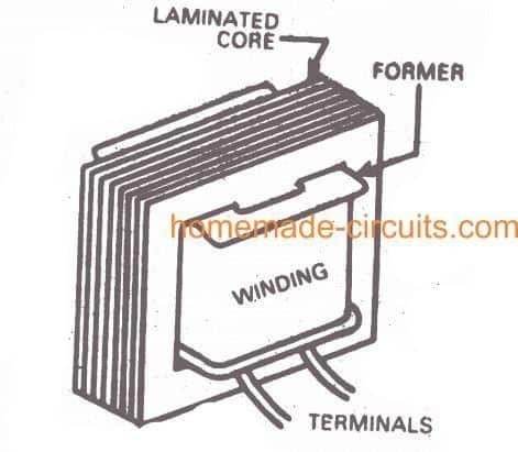
Small transformers possess a shell style structure, i.e. the winding are encircled by the core as demonstrated in Fig. 1.
The power supplied by the secondary is in fact transmitted from the primary, although at a voltage level dependent on the winding ratio of the a pair of winding.
Video Interpretation
Basic Transformer Design
As the initial phase towards the design of a transformer, the primary and secondary voltage evaluations and the secondary ampere rating has to be distinctly expressed.
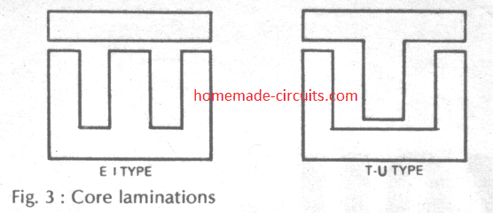
After that determine the core content to be employed: ordinary steel stamping or cold rolled grain oriented (CRGO) stamping. CRGO features a greater allowable flux density and reduced losses.
The best possible cross-sectional part of the core is roughly assigned by:
Core Area: 1.152 x √(output voltage x output current) sq cm.
With regard to transformers having several secondaries, the sum of the the output volt-amp product of each winding needs to be considered.
The quantity of turns on the primary and secondary winding is determined using the formula for turns per volt ratio as:
Turns per volt = 1/ (4.44 x 10⁻⁴ frequency x core area x flux density)
Here, the frequency is usually 50Hz for Indian household mains source. The flux density could be considered as approximately 1.0 Weber/ sq. m. intended for ordinary steel stamping and approximately 1.3 Weber/ sq. m. for CRGO stamping.
Calculating Primary Winding
The current in the primary'winding is presented by the formula:
Primary Current = Sum of o/p Volt and o/p Amp divided by Primary Volts x efficiency
The efficiency of small transformers can deviate between 0.8 to 0.§6. A value of 0.87 works extremely well for regular transformers.
The appropriate wire size needs to be determined for the winding. The wire diameter is dependent upon the current rated for the winding and also the permitted current density of the wire.
The current density could be as tall as 233 amps/ sq. cm. in small transformers and as minimal as 155 amps/ sq. cm. in big ones.
Winding Data
| SWG | Max. current capacity (Amp) | Turns per sq. cm. |
|---|---|---|
| 10 | 16.60 | 8.7 |
| 11 | 13.638 | 10.4 |
| 12 | 10.961 | 12.1 |
| 13 | 8.579 | 13.6 |
| 14 | 6.487 | 21.5 |
| 15 | 5.254 | 26.8 |
| 16 | 4.151 | 35.2 |
| 17 | 3.178 | 45.4 |
| 18 | 2.538 | 57.3 |
| 19 | 2.013 | 72.3 |
| 20 | 1.313 | 106.0 |
| 21 | 1.0377 | 132.7 |
| 22 | 0.8183 | 167.4 |
| 23 | 0.6383 | 210.9 |
| 24 | 0.5046 | 265.9 |
| 25 | 0.4004 | 334.9 |
| 26 | 0.3284 | 415.0 |
| 27 | 0.2546 | 523.0 |
| 28 | 0.2024 | 659.0 |
| 29 | 0.1608 | 830.0 |
| 30 | 0.1558 | 881 |
| 31 | 0.1364 | 997 |
| 32 | 0.1182 | 1137 |
| 33 | 0.1014 | 1308 |
| 34 | 0.0858 | 1608 |
| 35 | 0.0715 | 1902 |
| 36 | 0.0586 | 2286 |
| 37 | 0.0469 | 2800 |
| 38 | 0.0366 | 3542 |
| 39 | 0.0284 | 4838 |
| 40 | 0.0225 | 5595 |
| 41 | 0.0197 | 6543 |
| 42 | 0.0144 | 9337 |
| 43 | 0.0113 | 11352 |
| 44 | 0.0090 | 14392 |
| 45 | 0.0079 | 17147 |
| 46 | 0.0059 | 20223 |
| 47 | 0.0047 | 25397 |
| 48 | 0.0037 | 31605 |
| 49 | 0.0029 | 40160 |
| 50 | 0.0010 | 81242 |
Typically, a value of 200 amps/ sq. cm. may be considered, according to which Table#1 is created. The amount of turns in the primary winding is presented by the formula:
Primary Turns = Turns per Volt x Primary Volts
The room consumed by the winding is determined by the insulation density, technique of winding and the wire diameter.
Table#1 provides the estimated values of the turns per square cm. through which we are able to calculate the window area consumed by the primary winding.
Primary winding Area = Primary turns / Turns per sq. cm from Table#1
Calculating Secondary Winding
Considering that we have the assumed secondary current rating, we are able to determine the wire size for the secondary winding simply by going through Table#1 directly.
The quantity of turns on the secondary is calculated in the identical method when it comes to primary, but around 3% excess turns should be included to reimburse for the internal drop of secondary winding voltage of the transformer, upon loading. Hence,
Secondary turns = 1.03 (turns per volt x secondary volts)
The window area necessary for secondary winding is identified from Table#2 as
Secondary window area = Secondary turns / Turns per sq. cm. (from Table#2 below)
Calculating Core size
The principal qualifying measure in picking the core could be the total window area of winding space accessible.
Total window area = Primary window area + sum of secondary window areas + space for former & insulation.
A little extra space is necessary to support the former and insulation in between winding. The specific quantity of extra area may differ, even though 30% could be considered to begin with although this may need to be customized later on.
Table Dimension of Transformer Stamping
Section 1
| Type No. | Tongue width (cm.) | Window area (sq. cm.) |
|---|---|---|
| 17 (E-I) | 1.270 | 1.213 |
| 12A (E-I) | 1.588 | 1.897 |
| 74 (E-I) | 1.748 | 2.213 |
| 23 (E-I) | 1.905 | 2.723 |
| 20 (E-I) | 1.905 | 3.230 |
| 15 (E-I) | 2.223 | 3.230 |
| 31 (E-I) | 2.588 | 3.230 |
| 11 (E-I) | 2.540 | 4.839 |
| 35 (E-I) | 2.540 | 4.839 |
| 14 (E-I) | 2.461 | 5.645 |
| 33 (E-I) | 2.461 | 5.645 |
| 11 (E-I) | 2.540 | 7.259 |
| 35 (E-I) | 2.540 | 7.259 |
| 3 (E-I) | 3.810 | 7.562 |
Section 2
| Type No. | Tongue width (cm.) | Window area (sq. cm.) |
|---|---|---|
| 9 (U-T) | 2.223 | 7.865 |
| 9A (U-T) | 2.223 | 7.865 |
| 4A (E-I) | 3.810 | 10.484 |
| 4 (E-I) | 3.810 | 10.484 |
| 16 (E-I) | 3.810 | 10.891 |
| 13 (E-I) | 2.381 | 15.865 |
| 7 (E-I) | 2.540 | 15.865 |
| 6 (E-I) | 3.810 | 15.865 |
| 5 (E-I) | 3.810 | 19.305 |
| 8 (E-I) | 5.080 | 49.803 |
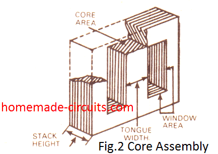
The perfect core sizes possessing a more substantial window space are generally determined from Table#2 taking into consideration the gap between lamination while stacking them (the core stacking element may be taken as 0.9), we now have
Gross core area = Core Area / 0.9 sq cm. In general, a square central limb is preferred.
For this, the width of the tongue of lamination is
Tongue width = √Gross core area (sq.cm)
Now refer to Table#2 once again and as a final point find the appropriate core size, having adequate window area and a nearby value of the tongue width as calculated. Modify thel stack height as needed to acquire the intended core section.
Stack Height = Gross Core Area / Actual Tongue Width
The stack must not be a lot under the tongue width rather should be more. However, it must not be greater than 11/2 times the tongue width.
Core Assembly Diagram
How to Assemble the Transformer
The winding are done over an insulating former or bobbin that fits on the middle pillar of the core lamination.
The primary is generally wound first, and next it is the secondary, keeping an insulation between the two layers of the winding.
One last insulating layer is applied on top of the winding to safeguard all of them from mechanical and vibration deterioration.
Whenever thin wires are employed, their particular ends needs to be soldered to heavier wires in order to bring the terminals outside the former.
The lamination are usually put together on the former by alternate lamination reversed in set up.
The lamination has to be tightly bound together through an appropriate clamping framework or by using nuts and bolts (in case through holes are supplied within the lamination assembly).
How to Apply Shielding
This can be a wise idea to utilize an electrostatic shielding between the primary and secondary winding to circumvent electrical interference from moving across to the secondary from the primary.
The shield for step down transformers can be constructed from a copper foil which can be wound between the two winding for somewhat more than a tum.
Insulation has to be presented across the entire foil and proper care taken in order that the two ends of the foil never come in contact with each other.
Additionally a wire could be soldered with this shielding field and connected with the ground line of the circuit or with the lamination of the transformer which may be clamped with the ground line of the circuit.
For Torroidal Transformer designing, you can refer to the following pdf document:
https://www.homemade-circuits.com/wp-content/uploads/2021/04/torroidal-transformer_compressed.pdf
Additional Useful Information Regarding Transformer Winding
The following useful data related to transformer winding was kindly shared by Mr. Constantinos Mermygas. I hope the readers will find it very helpful.
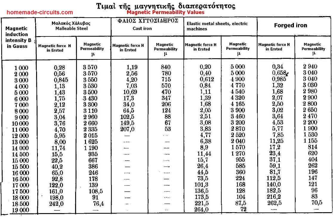
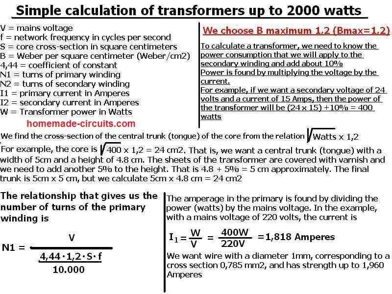
Simple Calculation of Transformers Up to 2000 Watts
Parameters:
- V = Mains voltage
- f = Network frequency in cycles per second
- S = Core cross-section in square centimeters
- B = Weber per square centimeter (Weber/cm²)
- 4.44 = Coefficient of constant
- N1 = Turns of primary winding
- N2 = Turns of secondary winding
- I1 = Primary current in Amperes
- I2 = Secondary current in Amperes
- W = Transformer power in Watts
Calculation Notes:
- Choose Bmax = 1.2 (maximum flux density).
- To calculate a transformer, determine the power consumption on the secondary winding and add approximately 10%.
Power Calculation Example:
- Secondary Voltage: 24 volts
- Current: 15 Amps
- Transformer Power: (24 * 15) + 10% = 400 watts
Core Cross-Section Calculation:
- Example:
Core cross-section: √400 * 1.2 = 24 cm²
Central trunk (tongue): - Width = 5 cm
- Height = 4.8 cm
- Add 5% for varnish, total height ≈ 5 cm
Primary Winding Turns Calculation:
- Formula:
N1 = V / (4.44 × B × S × f / 10,000)
Primary Current Calculation:
- Formula:
I1 = W / V
Example:
I1 = 400W / 220V = 1.818 Amperes
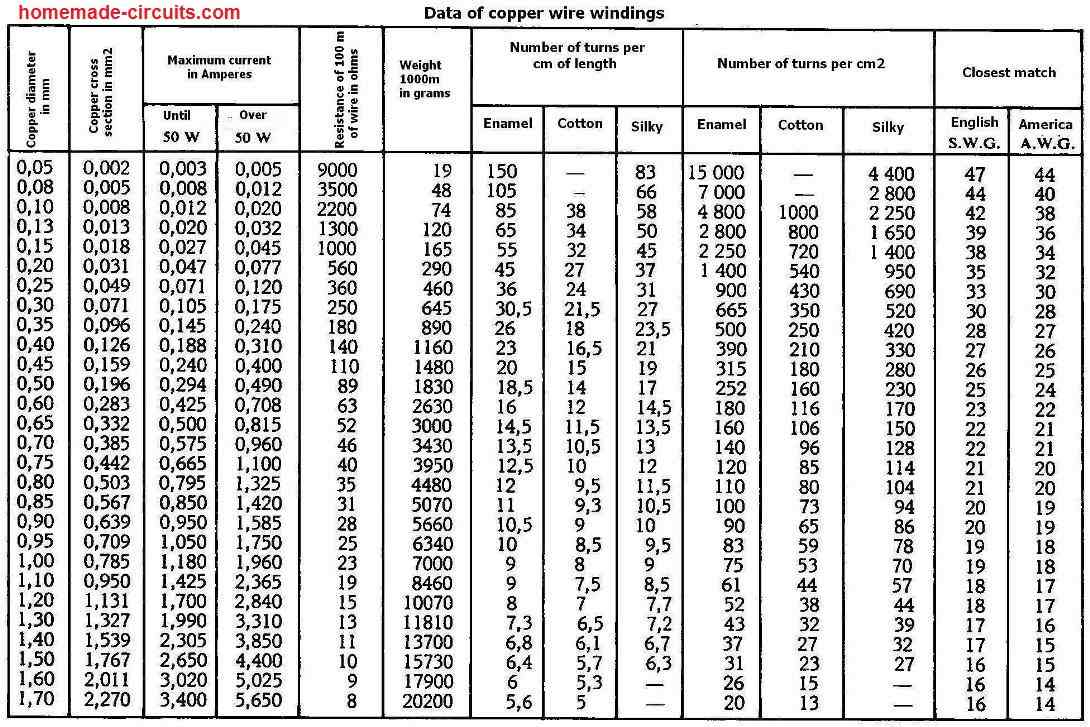
Wire Calculation:
- Example:
- Wire Diameter: 1 mm
- Cross Section: 0.785 mm²
- Current Strength: Up to 1.960 Amperes

Comments
Hello Swagatam
Thanks for your reply.
Now inverter 24v to 230v. 900va
CA=35cm2
TPV=1.0
Primary turns=24nos. 40amp 8swg
Sec turns=. 230nos. 4amp. 18swg
Now which bobbin and crgo EI core should I choose for the best result?
Hope you best
Happy New year
Hello JK,
I think only a transformer expert would be able to suggest you correctly about the exact dimensions.
Basically, Use a bobbin that matches the EI core size. For a 35cm^2 core area, the EI core size would likely be between EI 96 and EI 120.
Hello. Swagatam
Hope you fine
Core area,= 1.152 sqrt (VA)
HOW this formula is derived?
Thanks
Hi JK,
Output Voltage (V) is the voltage that comes out of the transformer’s secondary side.
Output Current (A) is the current that flows out of the transformer’s secondary side.
√(Output Voltage * Output Current) shows the apparent power (VA) of the transformer.
The number 1.152 is a constant and is derived by experimenting with the following factors of an iron core transformer::
Magnetic Flux Density (B): This is a common value for iron-core transformers usually between 1.2 and 1.5 Tesla.
Frequency (f): This refers to the usual mains frequency which is either 50 or 60 Hz.
Efficiency: Transformers don’t work at 100% efficiency in real life so this number helps to factor in losses from things like core saturation, hysteresis, and eddy currents.
Practical Design Adjustments: This includes industry standards and safety margins.
No mention is made about the weight of the core itself. I thought the weight of the core in kg is an important factor in power handling of the transformer.
Hi.. Swagatam Thank you for the great works.
I think for high power designs we can either slightly decrease or increase the Bmax value or Power (watt) value to see the Cross sectional area, and then Check if it’s the same measurements with our real transformers Cross sectional area.
And with that we can knw if the transformer can deliver the actual power using the formula provided.
Thanks David, you are correct, we can try that. Appreciate your feedback.
Hi sir, thank you for the information. I would like to ask how you derive the equation of core area to get 1.152 x √(output voltage x output current) sq cm?
Hi Julian, it is a standard formula, I do not have sufficient information regarding how the formula was derived.
I see, appreciate for your help!
nice and usefull information
hello sir plz can you confirm that 1.152 is what and where you get this value.
Hello Rajiv,
The 1.152 is a constant and is permanently included in the formula.
Thank you sir
Great article but I’m still a little confused and don’t want to get it wrong. I’d like to build a transformer, 220v primary @ 60hz, 80v secondary with a max draw of 135 amps. Is that doable? I need help with core size and winding diameter. I’m assuming at 135amps it will get very hot if something is wrong.
Any input is appreciated,
Thank you
I understand your requirement, but unfortunately the Tables in the above article support only upto 10 amp transformers, so 135 amp may not be possible using the above information
Sir please meking the 1chapter choke design
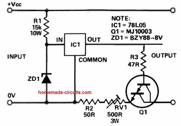
thank u sir , and can u pls share 16vdc to 14vdc 2n3055 transister based regulating power supply ckt diagram once.
Try the second circuit from this article:
https://www.homemade-circuits.com/how-to-make-current-controlled-12-volt/
Hi! I have been a fan of your work and i’m from the Philippines. I know it’s rude for me to ask but can you have sample calculation for a 750 watts transformer 50/60Hz that will be use in power inverter? I just want to have a sample and it serve as a guide as well. Hoping to hear your response soon! More power! \m/
Thank you so much Diltone, I appreciate your kind words.
Yes I have a sample article which explains how to wind an inverter transformer, however the maximum current is only 10 amps. Here’s the link for the article:
https://www.homemade-circuits.com/how-to-design-your-own-inverter/
Thank you for the quick response! I just want to ask since I haven’t read the article and the link you sent me but I just want to know how much wattage that 10 amps will deliver?
You can multiply 10 amps with the battery voltage, that will be the maximum wattage achievable from the transformer.
I have a transformer 50 kva 400/11000 v, if I doubled the low voltage turns, can I connect the low voltage side of the transformer to 800 volts source to step up to 11kv
Is there any issue will appear during operation
Yes, as per the transformer standard formulas, that should be OK and possible.
great tutorial! Thanks for sharing this. Have you done a tutorial on winding a 3 phase step up/down transformer? I’d like to use a VFD single phase to 3 phase inverter, but the output is 110vac. I need to step this down.
Any suggestions would be welcome!
Thanks
Doug
Thank you!
I do not have a 3 phase transformer tutorial yet. If posible I will rty to investigate it.
For converting a 110V AC to lower levels only a step down transformer would work and can be used.
yes, the step down seemed to be the logical way to go – but doing with 1 transformer would certainly be easier than using 3, separate transformers 🙂
Thanks again for your comments and efforts.
Doug
sir how many turns will be required for both primary and secondary sides of 0-6v 50amps center tap transformer
John, the maximum current that can be used is upto 10 amps according to the above article…there’s no data given above this value in the relevant tables.
I need to make an audio transformer for an old telephone. One winding is 15 Ohms the other is 75 Ohms. Voltage supply is 3 volts.
An exisiting transformer is cylindrical and is 4 inches long by 3/4 inch in diameter with a laminated core.
Is it possible to specify wire diameter and number of turns in each coil.
Thankyou
Rod
It can be difficult to suggest the number of turns, however the wire thickness on the 75 ohm side can be around 0.3mm and on the 15 ohm ohm this can be around 0.5mm
Since you have the resistance values for the respective winding, you can wind it by some trial and error until the specified resistance values are achieved.
Hello Swagatam
I will translate two tables, and send them to you.
They are elements, for electrical machines for Power up to 1250 KW
Note: I used a translator. I don’t know the English language
Thank you Constantinos, I appreciate your valuable feedback.
Thank you Arnold, Glad you found the post useful.
You can probably refer to the following post which explains a simpler method of calculating and configuring a transformer. Let me know if you have any further questions.
https://www.homemade-circuits.com/how-transformers-work/
Dear Sir,
i’ve read to wonderful explaination concerning the VA of a transformer, I like to learn more about the computation and design of transformer.
will you please send me some, that I may learn and make my own transformer.
your consideration is highly appreciated, more power to you Sir.
Hello Swagatam, and Constantinos thank you for your reply.
I didn’t feel offended at all. I only referred to a concrete example, of an old transformer that refers to the value in Amperes and not in “VA”s. I’m looking for components to build a power supply, and at the store they asked me how many “VA”s will I need in the transformer? And I couldn’t say… I answered 4, 5A at the most! In the store they weren’t able to suggest any or explain what the value in “VA” means and why it’s important. But now I know… thanks to you!
Greetings from Portugal.
Thank you for the explanation Constantinos! it is much appreciated. I hope the readers will find it useful.
Mr. Sagamatan, I don’t like to talk about myself, but now I am forced to do so, in order to raise the issue of translation.
Also, thank you for giving me the opportunity to explain some issues.
I teach through internet special course, in two schools outside Greece.
I have a lot of difficulty in translating when I have to convey the meaning of technical definitions.
The science of electricity includes a very large percentage of special way of thinking and words of philological type, and this makes the translation extremely difficult
Let me clarify that the concept of science is different from the concept of technology.
In a general context, science tries to interpret the fixed and unchanging laws of nature, while technology regulates the order in which the laws of nature are applied in conjunction with time, depending on the result we want to have.
“This”, how to explain it with scientific and technological terminology, and in another language?
Google translation is not to blame, because the problem starts with the words of the language that each person speaks, and the language helps the perception of the meaning.
I will give an example, although there are no correct words in English. Everyone talks about voltage and amperes, and to these two they give the meaning of power.
But, in the word “power” they do not give the meaning, but they give the unit of measurement.
The volt is the unit of measurement, not the force itself. Who is she is “this” force, and what is that a force?
In the Greek language, this force is called a tendency (Greek – “τάση” = trend in English). But the word trend has another meaning in the English language. So a correct translation cannot be made. But here I will speak with philological concepts and not with technological terminology.
When we have a material body (for example, a conductor) that has different electric charges at the ends of the body, then we say that the material body is in disequilibrium.
Another example: when a cloud has a different electric charge than the earth, then again we have an imbalance, but this imbalance is between two different materials.
The desire that the material body has to get out of imbalance, and to balance electrically, is called trend.
In simple words, the desire that a material body has to come to a state of equilibrium is called a trend.
In other words: the force that the body exerts on itself to balance is called trend, and we measure it in volts.
It’s desire, not voltage. Voltage is a measure of the body’s desire to balance itself electrically.
.
But I got tired, maybe some other time when I will have time and mood, I will continue, so that your readers will be better informed.
However, all that I mentioned is impossible to translate with technological terminology.
Hello Constantinos, I agree with you, translating and interpreting technical definitions from one language to another can be problematic, and unfortunately there’s no easy workaround to solve this issue.
Hello Swagatam
Hello João Sousa
I happen to know how to write the Spanish language, (I don’t know the pronunciation), so I know that translation is difficult when it comes to giving definitions of great importance with technical jargon, and the meaning of the words is not rendered correctly.
For example, if you ask me to explain the difference between electrical energy and electrical force, I won’t be able to help you because there are no corresponding words in English, nor in Portuguese, nor in Spanish that correctly convey the concepts.
This is why I can’t explain volt-amperes to you clearly.
Also, another difficulty is that, I don’t know the terminology of technology in Portuguese and English language.
Good morning from Greece.
You are welcome Joao! All the best to you.
Hi Swagatam and Constantinos, thank you for both replies.
Now I’m finishing my new training, and then I’ll decide the important parameters in the power supply I intend to build, as I was alerted here, for the various types according to their purpose.
I intend to build the power supply according to its specific purpose, as a final project of the basic training in Electronics that I started now.
Constantinos, you don’t need to worry about the translation into Portuguese either, your English / “Google English” is quite sufficient, your message has arrived without any problem. It’s just that I hate “Google’s Portuguese” translations; they don’t respect European Portuguese! … and I end up having to make an extra effort to understand.
Thank you Constantinos, for sharing this valuable information.
Hello Swagatam and Constantinos, Thank you very much for your detailed explanation.
Now I understand the difference.
Best wishes,
João Sousa
Hello again Swagatam
Hello again João Sousa.
Since you want to build a power supply, it would be good to tell us what the use of the power supply will be, and what you will power.
In DC power supplies we don’t need the power, neither in VA nor in watts.
The important thing we need to know is, what is the maximum voltage we want at the output of the power supply, and what is the maximum current we want at the output.
In order to have a correct power supply, we calculate the voltage separately, and the amperes separately.
When we are going to power electronic devices, the current, but mainly the voltage is strictly necessary.
In power supplies, volts have the main reason. If the voltage is too less, the electronic device will not work, while if the volts are more the electronic device will burn.
If you want a general bench power supply, for experiments and tests, it would be good to choose a variable voltage power supply. A bench power supply, (+30) – 0 – (-30) up to 1.5 amps, is sufficient for testings.
If you want a power supply for something very specific, tell us what you want to power so we can guide you precisely.
Note: The translation is also done in the Portuguese language for a better understanding of the concept
=================================================
Olá novamente João Sousa.
Como você deseja fazer uma fonte de alimentação, seria bom nos dizer para que você a usará.
Em fontes de alimentação DC não precisamos de VA ou watts.
O importante que precisamos saber é qual é a tensão máxima que queremos que a fonte de alimentação nos dê na saída e qual é a corrente máxima que queremos na saída.
Para ter uma fonte de alimentação correta, calculamos a tensão separadamente e os amperes separadamente.
Quando vamos alimentar dispositivos eletrônicos, a corrente, mas principalmente a tensão, é estritamente necessária.
Em fontes de alimentação, os volts têm o principal motivo.
Se a tensão for muito menor, o dispositivo eletrônico não funcionará, enquanto se os volts forem maiores, o dispositivo eletrônico queimará.
Se você deseja uma fonte de alimentação de bancada geral, para experimentos e testes, seria bom escolher uma fonte de alimentação de tensão variável. Uma fonte de alimentação de bancada, (+30) – 0 – (-30) até 1,5 amperes, é suficiente para o testes.
Se você deseja uma fonte de alimentação para algo mais específico, diga-nos o que deseja alimentar para que possamos orientá-lo com precisão.
No problem Joao! thanks for sharing your kind feedback!
Mr. João Sousa, I have some time and I thought I would give some additional explanations, regarding the transformers, so that the rest of the readers can be enlightened.
When calculating a transformer, the first thing we need to know is how and where we will use the transformer.
Otherwise we calculate a power distribution network transformer, else we calculate a transformer to power an audio amplifier, else we calculate a transformer of an electrical device, else we calculate a transformer for amplitude modulation of transmitters.
But to help you understand some differences, I’ll break down the power distribution transformer, which brings 220 volts to our home.
These transformers are of high power, typically 1,500,000 VA
But be very careful. These transformers are made for 250 volt secondary winding, not 220 volt.
When we connect the load (consumer), then the 250 volts low of energy absorption from the consumer becomes 220 volts.
Now suppose that the secondary current of the transformer can deliver 1000 amperes. 1000 amperes times 250 volts is measured in VA because it is the apparent power. While 1000 amperes times 220 volts (which is the actual applied voltage) we measure it in watts.
This calculation is done when you apply AC directly to a consumer, and here the differences between VA and watts are large, and it makes sense to calculate them.
But when we have a household transformer that will feed an amplifier, the calculation changes, 1) because we will rectify the current, and 2) because the capacitors after the rectification, increase the voltage by about 12%.
That is, a transformer that has an alternating secondary winding voltage of 12Vac, and 1 ampere, when we rectify it, we will have 12 volts times 1.41 = 16.92 volts. Plus the 12% increase from the capacitors, the voltage will reach 19.22 volts. Here it makes no sense to calculate the difference between VA and watts, and we calculate the power directly in watts.
At this point, look at the difference. we have another power before the rectification (12 volts x 1 ampere = 12 watts AC), and another after the rectification 16.92 volts x 1 ampere = 16.92 watts DC). Whereas 19.22 volts times 1 ampere = 19.22 VA, because it is the apparent power, not the real one.
The transformer essentially converts the characteristics of the power, but does not convert the power itself, nor the frequency.
When we have a transformer with a primary winding of 220 volts 1 amp, the secondary can give us (example) 22 volts 10 amps.
That is, the power in both primary and secondary is the same. I don’t mention the transformer losses due to currents inside the core, which appear as heat, because they belong 96% to the secondary.
Actually the transformer transfers the consumed energy (power) of the load, from the secondary to the primary winding, and the primary transfers it to the generator.
I don’t have any more appropriate words than that, and unfortunately google translation doesn’t help with technical terminology.
Note: To clarify that, I am not electronic. I am an electrician technologist, and a radiation radio-electrician. I visit Swagatam website for electronics, because I don’t know electronics science, and I find the website reliable.
I’ll start with the 220/110 Ω-12A transformer……If the transformer has a secondary voltage of 110V and 12A, then you’ve calculated correctly 1320VA .
I’ll try again, in other words. VA is the apparent power, i.e. what we see. Probably what the gauges see. But what we see is not always correct. While the watt is the real power, when we connect the load (the consumption).
When we calculate a transformer, we calculate it in watts, regardless of whether we connect a resistive consumer, or whether we connect an inductive one.
Also, VA is the operation of a multiplication. It might be 10 volts by 2 amps, but it might be 2 volts by 10 amps. the result in both cases is the same (20VA)
I have no intention to offend you, but these concepts are for people who have a lot of experience and advanced knowledge. Even electricians have a hard time understanding these concepts.
The transformer when it is above 2500 watts, is not something simple to calculate. But when he is smaller, the watts and the VA have little difference., and it is not worth bothering so much. Actually, I don’t do such detailed calculations either, and that’s my job.
But don’t confuse amperes with VA. Volts are the force that makes electrons move. While amperes are how many electrons move in a second second. But this is not going to help you at all. On the contrary, it will confuse you more.
These topics are discussed by mechanical-electrical , and radio-electrical engineers.
You, keep in mind that the VA is the same as the watt.
However, if you have any other questions, I’ll try to explain them to you.
My best wishes from Greece
Hello Swagatam and Constantinos, thank you for both replies.
I looked for more information on the subject, and found these two formulas:
I=U/R(A) and P=UxI(W)
And now I know that both can be related (in case the circuit is pure resistive, if it is for motors we also have to consider the value of cos(fi)), but when I read the article about the calculation of transformer windings, I didn’t find any reference to “VA”s , and I thought, after all, what are we calculating in practice? and how does it relate to the characteristics of prefabricated transformers that are on the market today?.
And to add to my doubt, I have an old transformer (Still working in a sewing machine, with the characteristics 220V;110V/12A).
In summary, at some point in time the value in Amperes was no longer used, to be replaced by VoltAmpere to designate the maximum operating value of a transformer for a given voltage value (in the “modern” designation it would roughly be, 110X12= 1320VA)
Best regards