The proposed remote control circuit idea can be used for controlling any electrical gadget within a range of 100 meters.
How the Circuit is Supposed to Work
Since the idea here is to modify an existing circuit of a remote bell unit, becomes super easy without any complications.
However the construction part does require the involvement of electronic assemblies so this project may not be considered entirely a layman’s project. We all have seen and probably used remote bell gadget in our homes.
The device is basically a wireless RF receiver and a transmitter set which can be used for producing alarm sounds remotely for calling or indication proposes.
These gadgets are pretty effective with their functions and the specified operations are done efficiently across a considerable distance.
The Chinese made remote bell units are best suited for the proposed project. Basically, when the transmitter of the remote bell is pressed, it sends a strong RF signal over a radial distance of approximately 100 meters.
The receiver unit positioned anywhere within this limit instantly plucks the trigger and switches the in built musical bell, sounding the alarm.
The trigger may last for a few moments even after the transmitter is switched OFF. The only feature that we are interested in is the effective transmission and receiving of the RF signals across the said distance.
If we are able to mod the receiver part of the unit so that the received trigger can be used to operate a relay instead of the usual alarm, our job is done.
However before we indulge into the modification process, it would be necessary to make the Flip Flop circuit first, which would be later on required to be integrated with the receiver set of the remote bell.
The flip flop section is a very simple configuration consisting of just a single IC and a few other passive components.
The entire circuit may be buikt over a small general purpose board with the help of the shown schematic.
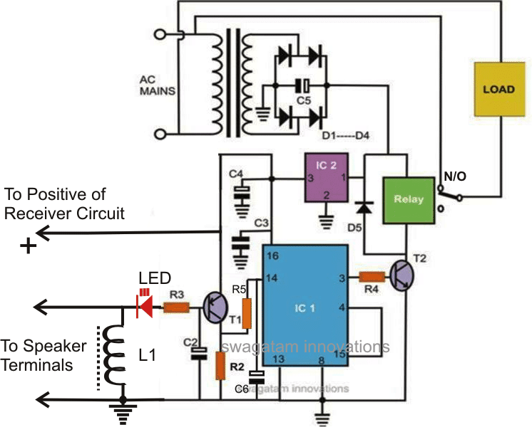
Circuit Diagram
Modifying the Receiver (Rx) of the Remote Bell
On opening the cover of the remote bell receiver unit, the following things may be traced out for commencing the modding process:
You will find a small speaker connected via a couple of wires which terminate from the circuit board of the unit.
Just cut-of the wires from the speaker, remove the entire circuit from its housing and screw it inside a new housing, which should be relatively bigger in size so that it can accommodate the flip flop section, the transformer power supply section and also the relay assembly.
After locating the negative wire out of the two speaker wires, integrate them to the flip flop circuit appropriately as shown in the figure.
Once the connections are made as per the schematic, check the system by powering the unit and by making a few triggers via the transmitter module.
The relay can be seen toggling in response to each subsequent triggers made by the transmitter module.
Your RF remote control circuit is ready and may be used for controlling any electrical gadget that you may prefer, wirelessly, across a radial distance of around 100 meters.
Parts List for the Circuit Diagram The following listed parts will be required for making the above explained RF remote control circuit's flip flop section:
Parts List
R3 = 100 ohms,
R2 = 100K,
R4 = 4K7,
R5 = 10K,
C1, C2, C4= 22uF/25V,
C6 = 4.7uF/25V,
C3 = 0.1, CERAMIC,
C5 = 1000uF/25V,
T1 = BC557B
T2 = BC547B,
ALL DIODES ARE = 1N4007,
L1 = 50 turns of 30 SWG super enameled copper wire wound over a any ferrite material.
IC1 = 4017,
IC2 = 7805,
TRANSFORMER = 0-12V/500mA,


Comments
Hi Swagatam, You have helped me out with a circuit already, a motion sensing detector circuit that switches off in the day – thanks ! I have a new challenge, how to use a motion detector at the front gate of the house to sound an audible alarm inside the house (wirelessly). The above circuit looks a bit complicated and I don’t have any remote bell circuits hanging around. Any suggestions would be appreciated – Thanks.
Thanks Andy, I think the easiest idea would be to buy a ready-made pair of remote bell Tx/Rx units, then couple the Tx (transmitter) unit’s bell switch wires with the relay contacts of your proximity detector circuit. Once this is done, each time the proximity relay clicks will result in an alarm sound from the Rx unit of the remote bell.
I have place all the new components on the shematic, I do not find the place for R1 : 100 ? I will send you the new shematic after.
Norman
sorry R1 is mistakenly included in the parts list, please ignore it as it is not there in the schematic, I’ll correct the parts list soon
From where can i get L1 or will it work without L1
brother can i use all capacitor rated 50v??
yes that will do, even twice the value of the supply voltage will be safe.
it's the positive supply rail of the radio where the + of the battery or the AC/DC adapter is connected for powering the radio