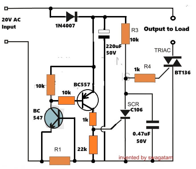
In this post I will try to explain the making of a simple 220 V, 120 V AC mains short circuit breaker using an SCR and a triac combination, (researched and designed by me).
The circuit is an electronic version of the normal main circuit breaker MCB units that we use in our homes.
Note: I did not use a relay for the cut-off, because relay contacts will simply fuse with each other due to heavy current arcing across the contacts during a short circuit condition, and therefore it is highly unreliable.
Why Short Circuit in Homes Can be Hazardous
A short circuit in a house wiring may appear to be something which happens very seldom and folks aren’t too interested to get any relevant precautionary measure installed in their houses and take the hazard very casually.
However once in a while due to some accidental fault, a short circuit in the mains wiring becomes inevitable and it the happening causes a disaster and huge lose.
At times the consequence leads to fire hazards and even lose of life and property.
WARNING - THE PROPOSED CIRCUIT IS NOT ISOLATED FROM MAINS AC, THEREFORE IS EXTREMELY DANGEROUS TO TOUCH IN UNCOVERED POSITION AND WHEN POWERED.
Though many types of short circuit breaker units are available ready made in the market, these are generally very costly.
Moreover an electronic hobbyist will always want to make such an equipment all by him and enjoy its display in the house.
Electronic MCB Circuit Using a Solid State MOSFET SSR
This promising electronic MCB circuit is designed by me, which works as series solid-state electronic circuit breaker for 220V AC mains. It is connected in line with mains, so when it cuts, load is fully disconnected.
Audio/Video Representation
Circuit Diagram

How MOSFET And Bridge Rectifier Work
MOSFET together with bridge rectifier behaves like bidirectional solid-state relay. AC input is applied in series with load, and load is connected across 220V AC output terminals. As long as MOSFET remains ON, mains power flows normally to load, nothing blocked.
DC Supply And Normal Operation
Small DC supply is taken from mains using dropper resistors and 12V zener. This DC is only for MOSFET gate bias and sensing circuitry, not for load. Under normal conditions MOSFET gate gets enough voltage, so IRF840 stays fully enhanced. MOSFET stays conductive during both half cycles of AC waveform, therefore load runs normally.
Current Sensing Using Rx
Load current flows through low-value resistor Rx at MOSFET source. During normal operation, voltage across Rx is very small and stays below SCR trigger level. So SCR remains OFF and MOSFET gate bias stays safe.
What Happens During Overload Or Short Circuit
When overload or short circuit happens, then load current rises sharply. Because of this, voltage across Rx also rises. When this voltage crosses SCR gate trigger threshold then SCR fires and latches immediately.
As soon as SCR turns ON, then it pulls MOSFET gate to ground. Gate-source voltage collapses, MOSFET goes into cutoff. Since MOSFET is in series with mains, turning it OFF instantly disconnects load from AC supply.
SCR stays latched even after overload disappears, means that MOSFET remains OFF permanently. So power must be removed briefly to reset circuit and bring it back to its original condition. This gives proper breaker-like behavior and protects mains wiring and load from overheating or damage.
Mathematical Derivation Of Rx
Trip condition depends on SCR gate trigger voltage.
For C106 SCR
Typical gate trigger voltage ≈ 0.6V to 0.8V
Design safely around 0.7V
Basic relation
Trip current = SCR trigger voltage / Rx
Rearranging gives:
Rx = SCR trigger voltage / Trip current
Example Calculations
For 5A trip current
Rx = 0.7 / 5
Rx = 0.14 ohms
For 10A trip current
Rx = 0.7 / 10
Rx = 0.07 ohms
For 15A trip current
Rx = 0.7 / 15
Rx ≈ 0.047 ohms
Power Rating Of Rx
Power dissipated in Rx
Power = I² × Rx
For 10A and 0.07 ohms
Power = 10² × 0.07
Power = 7W
That means Rx must be:
- Low-inductance
- Wire-wound or metal strip
- Rated at least 2× calculated power, so 14W recommended here
MOSFET Upgrade Tips
Here IRF840 works, but it runs close to SOA limits during overload switching. If we use better parts then it can give more reliability.
Direct Silicon MOSFET Upgrades
- IRFP460
- 500V, much higher SOA
- Lower Rds(on)
- Drop-in logic-wise
- STW11NK90Z
- 900V rating
- Excellent avalanche robustness
- Is designed for offline SMPS abuse
SiC MOSFET Options
- C3M0065090D (Wolfspeed)
- 900V SiC
- Very high dv/dt tolerance
- Almost immune to secondary breakdown
- C2M0080120D
- 1200V rating
- Very large SOA margin
- Good for inductive and harsh loads
SiC MOSFETs reduce switching losses, dv/dt false triggering and thermal stress during trip events.
Failure Mode Analysis
MOSFET Short Failure: If MOSFET fails short, then load stays permanently connected and protection is lost. Mitigation is actually simple, so always use upstream fuse or MCB.
SCR False Triggering: Noise spikes or dv/dt can cause false triggering, then nuisance trips may happen. Mitigation is small RC filter at SCR gate or tighter PCB layout.
Rx Open Circuit: If Rx goes open, then no current sensing, SCR never triggers. Mitigation is using robust shunt resistor, avoid thin wire types.
Bridge Rectifier Failure: One diode open gives half-wave operation. One diode short causes MOSFET overstress. Mitigation is using high surge diodes, so maybe 1N5408 is the minimum we should use.
Thermal Runaway: Continuous current near trip threshold heats MOSFET. Rds(on) increases, then shutdown may delay. Mitigation is good heatsinking and keeping Rx threshold margin lower.
Another Cheap yet Promising Electronic Circuit Breaker Unit
A short circuit breaker circuit I have I have explained in this article is indeed a piece cake as far making it is concerned and once installed will provide a life long protection against all short circuit like conditions that might accidentally take place.
The circuit will also safeguard you house wiring against a possible overload conditions.
How it Works
The circuit shown in the schematic looks pretty straightforward and may be verbally simulated as follows:
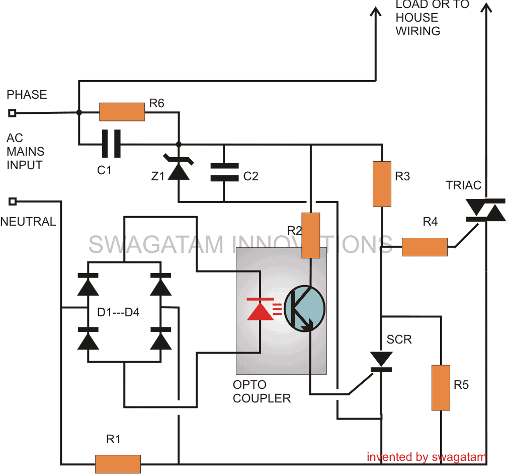
The sensing stage of the circuit in fact becomes the heart of the whole system and consists of an opto-coupler OP1.
As we all know, an opto-coupler internally consists of an LED and a switching transistor arrangement, the transistor is switched ON in response to the illumination of the built-in LED.
Thus the triggering of the transistor which forms the output of the device takes place without any physical or electrical contact rather through the passage of light rays from the LED.
The LED which becomes the input of the device may be switched through some external agent or a voltage source which required to be kept aloof from the output stage of the opto-coupler.
Why an Optocoupler is Used
In our circuit, the opto coupler LED is powered through a bridge network which obtains it voltage source from the potential generated across resistor R1.
This resistor R1 is connected in such a way that the AC mains current to the house wiring passes through it and therefore any over-load or over-current is subjected over this resistor.
During an over load or short circuit conditions, the resistor instantly develops a potential across it, which is rectified and sent to the opto coupler LED.
The opto LED immediately illuminates, switching ON the corresponding transistor.
Using an SCR for triggering the main Triac Cut out Stage
Referring the circuit we see that the opto transistor’s emitter is connected to the gate of an external SCR, whose anode is further connected to a Triac's gate.
During normal conditions, the triac remains switched ON, allowing the load connected across it to remain operational.
This happens because the SCR remains switched OFF and allows the triac to acquire its gate current through R3.
However in case of an over load or a short circuit, as discussed earlier, the opto-coupler transistor conducts and triggers the SCR.
This instantly pulls the gate potential of the triac to ground, inhibiting it from conducting.
The triac immediately switches OFF, safeguarding the load and the house wiring to which it is configured.
The SCR remains latched, until the problem is rectified and the circuit is restarted.The section comprising C1, Z1, C2 is a simple transformerless power supply circuit, used for powering the SCR and Triac circuit.
Parts List
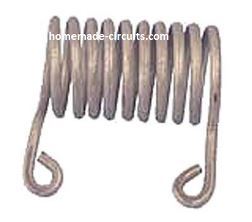
- R1 = iron coiled wire; its resistance is calculated to produce 2 volts across it at the determined critical load conditions.
- R2, R3, R4 =100 Ohms
- R5 = 1K,
- R6 = 1M,
- C1, C2 = 474/400V
- SCR = C106,
- Triac = BTA41/600B
- Opto-Coupler = MCT2E,
- ZENER = 12V 5W
- Diodes = 1N4007
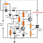
Another Improved Design

This design protects the load from sudden short circuit, heavy overload, and inrush surge. When fault happens then it reacts fast, so the load stays safe.
AC 220V or 120V enters through NTC. When power is ON then NTC limits initial surge. After that 0.33uF / 400V X2 capacitor drops current, 1N4007 rectifies, 12V 2W zener regulates, 220uF filters. So now around 12V DC is available for control section only.
Load is in series with BTA41 TRIAC. When gate gets trigger then it conducts AC. If gate drive is removed then it turns OFF at next zero crossing. The 100 ohm + 0.1uF snubber and 100 ohm 5W resistor suppress spikes. If noise appears then false triggering is prevented.
Rs is in series with load return. If load current increases then voltage across Rs increases. That voltage goes to MPSA42. Under normal load voltage is small, so MPSA42 is OFF. If overload happens then voltage rises and when it crosses base-emitter level then MPSA42 turns ON.
When MPSA42 turns ON then MPSA92 activates. This triggers C106 SCR, which then diverts gate drive from TRIAC. If gate drive is removed then TRIAC stops at next zero crossing so load disconnects.
Since SCR is latching, once it turns ON then it remains ON. To reset, mains must be switched OFF and ON again.
During short circuit, current rises sharply, then Rs voltage rises, MPSA42 turns ON, MPSA92 activates, SCR triggers, TRIAC gate drive is removed, TRIAC stops, load disconnects.
BTA41 is used because it handles high current and heavy load.
This circuit works directly on live mains. No isolation. Therefore handling must be careful.


Comments
Hello Sir,
A very interesting circuit. How could it be modified to handle an input voltage of around 20V AC, with max operating current of around 5A?
Kindest Regards,
Leno
Thanks Leno,
Is your load a DC load or AC load? Please specify, I will try to figure it out…
Hi Swagatam,
Thank you for replying.
It would be an AC load consisting of one or more DCC (Digital Command and Control) chips, as used on a DCC Model Railway. A DCC controller supplies the source AC voltage (which also contains coded information). This AC voltage is fed to all the track circuits at once. If one track circuit gets a short across it, then all the other track circuits will short at the same time. The idea is that each ‘circuit’ gets is own protection. Hope that helps?
Thank you Leno, for the clarification,
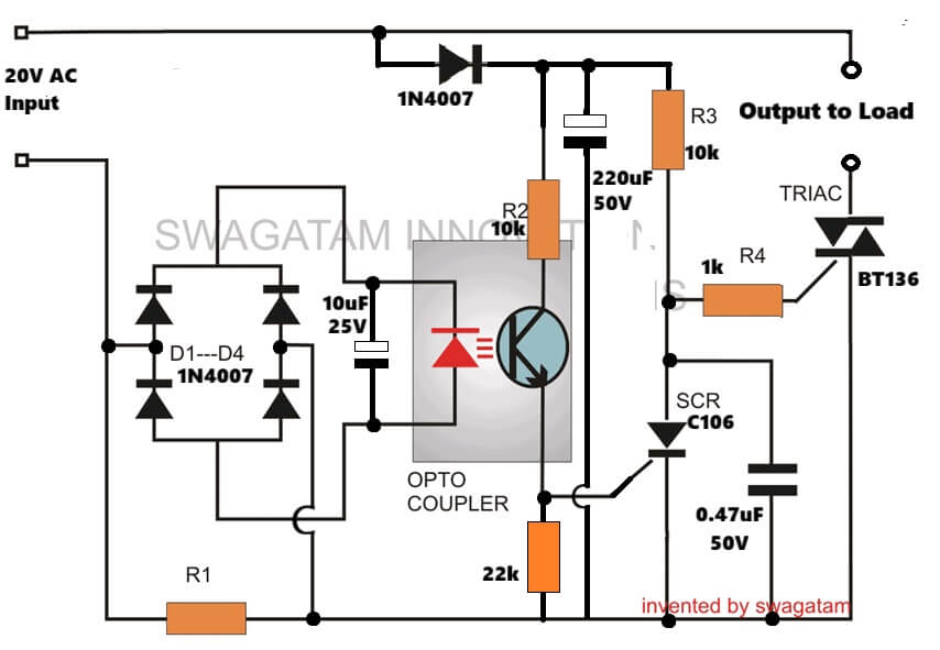
In that case, the think the following design should be able to fulfil your requirement, let me know if it works or not:
Leno, the circuit can be further simplified in the following manner:
Thank You,
Please give me a bit of time to acquire the components, and put it altogether, and I will get back to you ASAP.
Sure, no problems, all the best to you…
hello swagatam i am wondering if it is possible to add some sort of adjustable amperage setting to this. thanks for your comment in advance nice circuit too.
Hi Michael,
It can be done by replacing R1 with multiple parallel resistors of different values corresponding to different current ranges, and then use a rotary switch to select the appropriate resistors, as per requirements…
Sir, is there wattage rating for resistor used in this circuit?
How many ampere does a diode required?
Would love to know.
Hi Warrene, all resistors are 1/4 watt 1% MFR rated…
Diodes are 1N4007.
Good morning sir, I am fascinated with this particular invention of yours. I would like to adopt this invention and embed in our system we are working on.
If i may, could you please narrate how each components work.
I would like to cite you as the inventor of this particular module.
I would love to have your positive response. If you have a complete circuit diagram of this. You can reach me out at denmarkwarrenealulod@gmail.com or at my personal email at, denmarkwarrenealulod@hotmail.com.
respectfully,
DWPA
Hi Denmark, the circuit works in this way:
C1 drops mains current to a lower acceptable level.
Z1 regulates the half cycles to 12V and sends it to C2.
C2 filters it to make it clean DC 12V.
R2 sends this 12V DC to opto coupler transistor, R3/R4 sends this 12V to the triac gate.
The triac now turns ON with this 12V gate voltage and operates the load.
When an overcurrent or overload happens, this high current passes through R1 and causes an proportionate amount of AC voltage to develop across R1.
This small voltage is rectified into DC by the D1—D4 diodes and applied across the LED of the optocoupler.
Due to this opto LED lights up and turns ON the internal transistor, causing the 12V from R2 to enter the gate of the SCR.
The SCR now turns ON and latches ON permanently, and this grounds the gate voltage of the triac, turning it OFF, and this also turns OFF the load, preventing the overcurrent situation and any kind of fire hazards.
Good afternoon sir, i did a simulation at multimism simulator environment and the circuit works, the problem is that the R5 must be at 3W for it to work, else if 0.25 W is used, the R5 will be toasted under normal operation.
Thanks Denmark, are you referring to the R1 current sensing resistor, because R5 does not need to be 3 watts, it can be simply a 1/4 watt resistor. R5 has R3 in series so it can never burn…
It seems off, since in the simulator the voltage running on R5 is almost 16-17V which make the resistor getting toast. I’m not quite sure if the simulator has a problem in the logic side, meaning the simulator is not that accurate. Though the logic that cuts the power when overload occurs is there, and that’s a good scenario.
Also, kindly leave your full name sir.
TIA.
Respectfully,
D.W.P.A
Thanks for your analysis, I think the simulator is correct. The high voltage may be coming through the triac gate during the negative cycles. Please try replacing the R5 with a 0.1uF/400V PPC capacitor. This R5 or the capacitor just ensures a stable gate signal for the triac.
My full name is Swagatam Harry Majumder.
no protection exist for a phase to ground fault! The ground wire may neede no protection
Hi Mr. Swagatam;
As known we use a serial bulb for safety measurement against if the circuit is short / faulty. So far I used that practice for the 220V AC circuits But now this time I need to test the 110V AC circuit and all the bulbs which I have are for the 220V AC purpose. Is it possibe to use parallel 2 bulbs for the 110V circuit test?
Hi Suat, that looks OK to me. You can use two 220V bulbs in parallel to create an 110V equivalent.
Hi Swagatam;
As the sample there is a circuit in which AC 220 and DC 5 V are together at the PCB as in the circuit AC load with BT136 triggered by DC volt. It is possible to say about that for example the DC electronic parts would be negatively affected by AC voltage(i.e. magnetic field interaction). So we should add some parts to circuits like coils for the isolation of AC and DC. Kind Regards.
Hi Suat,
for the components there will be no effect at all, but for a human it can lethal to touch any point in the circuit.
When you use a triac with a DC circuit without an optocoupler then you will have to involve one AC line as the common line in the circuit. It is a standard practice.
There’s no need to add any extra parts in the circuit.
Sir, how can i achieve this the same purpose ( short-circuit, & over current protection) using arduino ?
Godstime, My Arduino knowledge is not good, so not very sure how that can be done!
Okay.
Thank you sir.
Goodnight
In the circuit, you can replace the scr and transistor optocoupler with an scr optocoupler, such as 4n40 that already has scr internally
Thanks in advance for your attention
Yes, I think it can be worth trying an optocouper with an internal SCR, so that the external SCR can be avoided.
Goodnight
thanks for the answer
The circuit is not tripping..
What should be done now????
Is the SCR switching on when the maximum current limit is reached? You can connect an LED in series with R2 to check this….If this LED does not light up means your opto is not working or there’s some other fault.
Hey,
We practically made this practically but a problem is there The MCB is tripping before this ckt.
So what should we do now???
Hi, to verify the working of the circuit, you can increase the value of the resistor R1 to some higher value. MCB is highly sensitive and fast so it may trip quickly…increasing R1 might help to complete the preliminary tests.
Can’t we replace R1 coil with a simple resistor??
If yes then how to calculate the resistance of that resistor or which resistor to use as R1
R1 handles the full output load therefore needs to be rated high, depending on the load current. You can try a wire wound resistor, using the following formula:
R1 = 2.2 / tripping current.
Assuming tripping current is for 2000 watt / 220V load, then 2000/220 = 9 amps or 10 amps.
R1 = 2.2 / 10 = 0.22 ohms
wattage will be 2.2 x 10 = 22 watt.
so yes using a wire wound resistor is feasible for R1.
Can you please tell me which wires to use to build this ckt. And how to safely test it…
I want to do this as my Minor Project in my Diploma Course..
Sorry I did not understand what you meant by “wire”….by the way this is not a minor project, since it involves AC mains which is not isolated and there may be a possibility of a fire hazard if not done correctly.
This circuit is recommended for the experts who know how to handle mains AC circuit safely.
Ok, advice taken..
So can you please suggest me a good idea for the project.
You can go with any project which is not dangerous in terms of shock or fire hazard. There are plenty of projects already explained in this site….you can select any one of them…
Hello,
I didn’t understand how the voltage cross the diode bridge to the led of the opto coupler since the diodes are opposite to the voltage direction.
Can you explain it please?
Thank you
Hello, yes the opto LEd polarity is wrongly shown in the diagram, it should be the opposite way….LED anode towards to the bridge cathodes, and LED cathode towards the bridge anodes
The LED voltage is 6V, the AC current I want to draw is 2A, so the R will 3ohms. Sir, is this correct.
Also, how can I make the iron coil and measure it.
Please Swag, Is there any easier way.
Thanks Sir
The LED voltage looks too high, the LED voltage should not eb more than 2V. So please change the LED accordingly.
for 2V, the value of the resistor will be 2 / 2 = 1 ohm / 4 watts
It will require a small pulse transformer in series with the SCR, which will provide a negative pulse to the triac to switch it OFF instantly….but the results will need to be confirmed practically.
Have you found any solution yet..
Hi Seun, the LED is inside the opto-coupler, the specifications can be checked from the datasheet of the selected device….
Good day Sir, please sir what is the value of LED Voltage rating to calculate R1.Thanks
If you connected it in series with the DC supply of the circuit then it is not supposed to affect the working of the circuit
Just asking does diode affect sensitivity of breaker, because there was a short circuit from a load that affected the MOSFET and the breaker failed to trip off,which used to trip before the diode was placed.
without seeing the schematic and the position of the diode it can be difficult to tell how the MOSFETs blew.
No schematic, I just connected diode to circuit breaker to give unidirectional path. Please does that affect as requested above.