The LM338 is an adjustable 3-terminal positive voltage regulator capable of providing up to 5 amperes of output current. To increase the output current capability, you can connect multiple LM338 ICs in parallel.
When you connect them in parallel, each IC will share the load current, allowing you to achieve higher total current handling capacity.
Here's a step-by-step guide on how to connect IC LM338 in parallel:
Note: When working with electronic components and circuits, always follow proper safety precautions. Double-check the datasheet and specifications of the LM338 IC for your specific application.
Materials Needed:
LM338 voltage regulator ICs (as many as needed for your desired current capacity)
Heat sinks for each LM338 IC
Suitable transformer and rectifier circuit to provide input power
Capacitors for input and output filtering (optional but recommended for stability)
Step 1: Heat Sinks
Ensure that each LM338 IC has an appropriate heat sink to dissipate heat effectively. The heat sink's size and thermal characteristics should be selected based on the maximum current and temperature rise requirements of the LM338 IC.
Step 2: Input Power Supply
Use a suitable input power supply to provide the required voltage and current for the all parallel connected LM338 ICs. This will require a transformer to step down the AC voltage, a bridge rectifier circuit to convert AC to DC, and input filter capacitors to smooth output the voltage.
Step 3: Provide Input and Output Capacitors (Optional)
You may add capacitors to the LM338 IC to improve its performance and maintain the power stable.
Connect one capacitor to the input of each LM338 and a second capacitor to the ground pin of the devices.
Connect another capacitor to the output of each LM338 and the ground pin of the devices. Simply select the capacitor sizes that apply to your device and refer to the datasheet for recommendations.
Step 4: Connect the LM338 ICs in Parallel
To connect the LM338 ICs in parallel, follow these steps in accordance with the following circuit diagram:
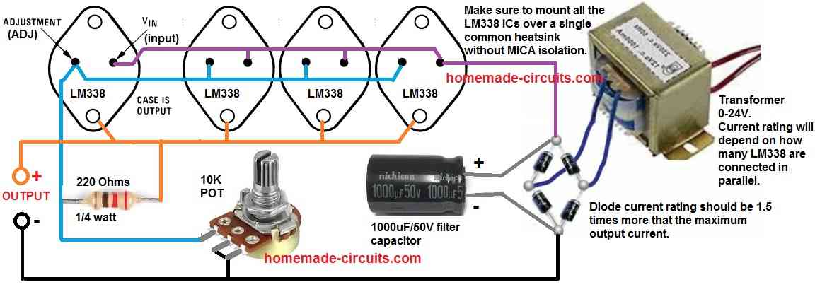
- Connect the Adjust (ADJ) pins of all the LM338 ICs together.
- Connect the Output (OUT) pins of all the LM338 ICs together.
- Connect the Input (IN) pins of all the LM338 ICs together.
- Connect a 120 ohm or 220 Ohm resistor between the outputs of the all the LM338 and the ADJ pin of all the LM338 ICs.
- Connect a 10 K potentiometer between the ADJ connections of all the LM338 ICs and the common Ground line.
Step 5: Individual Current-Limiting Resistors (Optional)
If you want to balance the load current between the parallel-connected LM338 ICs, you can add small current-limiting resistors in series with the ADJ pins of each IC.
This can help ensure that each IC contributes proportionally to the total output current. The value of the current-limiting resistor can be calculated using Ohm's law based on the desired current-sharing ratio.
Step 6: Mount the LM338 ICs on Heat Sinks
Mount each LM338 IC on its respective heat sink using suitable thermal compound and hardware. Ensure that the heat sinks are properly insulated to avoid any short circuits.
Step 7: Test and Monitor
Before connecting the load, test the parallel connection of LM338 ICs with a low current load and monitor the output voltage and current.
Ensure that the load is within the safe operating limits of each IC and that the output voltage is stable and regulated.
By following these steps, you can connect IC LM338 in parallel to increase the current-handling capability for your application.
Always refer to the LM338 datasheet and application notes for specific guidelines and precautions.


Comments
I hate to sound like a moron. But bear with me … send me the pictorial with 3 LM338 connected in parallel showing the resistors connection for 5 amps per regulator.
You a beautiful color pictorial showing the 3 LM338 in parallel … why can’t you modify that pictorial showing the load sharing resistors as well, Show a value(S) closest to 100% load sharing as possible.
I have already sent it to you, please check your previous emails.
https://www.homemade-circuits.com/wp-content/uploads/2023/07/how-to-connect-LM338-in-parallel-for-increased-current-output.jpg This the schematic I’m referring to on your post. Please reply back with the Adjustment pin resistors that will equalize the current share loading. The schematic you returned ti totally different. Perhaps you can redraw the pictorial schematic showing the adjustment resistors.
You just need to connect a calculated resistor in series with the outputs of the ICs, that’s all…
here’s the diagram:
https://www.homemade-circuits.com/wp-content/uploads/2025/05/LM338-in-parallel-using-series-resistors.jpg
2nd Request. Please show the schematic of the addition of the resistors in the adjustment pins that would provide load sharing. Just making a comment doesn’t make it obvious.
For Paralleling 3 LM138K Regulators.
You need to connect the resistor in series with the output of the IC, as shown in the following article:
https://www.homemade-circuits.com/make-25-amp-solar-battery-charger-power/
Please show the schematic of the addition of the resistors in the adjustment pins that would provide load sharing. Just making a comment doesn’t make it obvious.
Can current be adjusted as well? Can we make it provide constant current or voltage?
Yes, it can be adjusted by adding a Bc547 current sensing stage, as shown below:
https://www.homemade-circuits.com/wp-content/uploads/2025/04/current-control-voltage-control-with-parallel-LM338-resistors.jpg
Hello from Italy. I have a large toroidal transformer of 225VA and 28.5V output. Can I use this circuit without problems with about 38V DC input? In this case is it better to insert the small resistors in series with the ADJ pins of each IC? Thank you
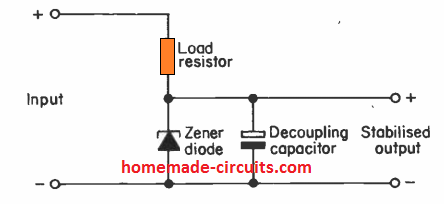
Hello Giuseppe, I won’t recommend using 38V input for an LM338 IC. Instead you can regulate the 38V to 35V using a transistor zener regulator circuit and then supply the fixed 35V to the input of the LM338.
You can use the following type of of regulator circuit.
https://www.homemade-circuits.com/wp-content/uploads/2021/11/single-transistor-voltage-regulator.jpg
Thank you very much, a practical solution to not change transformer and effective, Merry Christmas and Happy New Year
You are most Welcome…and a Merry Christmas and Happy New Year to you too!!
Hi Mr. Swagatam;
If we prefer to use the step 5 condition (using the individual current limiting resistors) then would the 10K pot be remain or removed?
Hi Suat,
The 10k pot is for adjusting the output voltage so it will be always required in the design, it cannot be removed.
Sorry I made a mistake, I thought that this was designed to adjust / control the output current instead of increasing the output current. Thanks anyway.
No problem Suat, Glad it is clear now!
Thanks for the interesting article! You say the transformer current rating depends on how many LM338s are connected, but I am not sure how to apply that. Are transformer current ratings based on input or output current? Where in this circuit (input of transformer, output of transformer, after bridge rectifier) would I put a fuse?
Each LM338 can handle upto 5 amp current. Suppose you needed 15 amp current output then you would use 3nos of LM338 in parallel. This would also means that the transformer would need to be rated at 15 amps.
You can put the fuse at the mains AC input side of the transformer.