Controlling your door lock through your personal cell phone was never this easy. Learn how to build a simple electronic circuit that will help in converting your ordinary door lock into a high security door lock which can be now controlled through your own cell phone.
Your ordinary door lock can be now very easily converted into a cell phone controlled high security door lock. Learn the entire building procedure through some simple instructions and circuit schematics.
Introduction
A very simple configuration using a low cost cell phone (used as a modem) and an electronic circuit can be build to control remotely a high security door lock.
Once the unit is built and attached to a door, by simply assigning your personal cell phone’s number inside the modem cell phone, you can alternately lock and unlock a particular door by sending subsequent “miss calls” through your cell phone to it from any part of the world.
We use a NOKIA 1202 as the modem cell phone here for the project. Let’s proceed and learn the simple instructions required to complete the project.
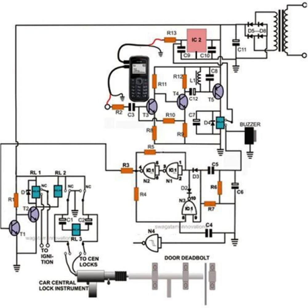
How the Circuit Functions?
The basic concept of the project is to detect a particular ringtone from a SIM supporting modem and use it to toggle the electronic circuit and the load (door lock) correspondingly.
The very specific and unique ringtone – “Beep Once” or the “No Tone” is available with every NOKIA cell phone. And also this ring can be assigned to any particular fed number of the cell phone.
So this ringtone becomes specific only to that particular number and will be sounded every time a call is received from the assigned number.
This facility has been ideally exploited here. A 5 volt regulated supply is used to trickle charge the modem round the clock so that its battery is never discharged.
This supply also goes to the IC 4093 = pin 14 (+) and pin 7(-). An in-built cut-off system inside every NOKIA cell phone ensures a safe charging.
The circuit functioning may be easily understood with the following explanation.
The FIGURE above shows a simple three transistor amplifier circuit which is basically used as a tone amplifier.
On receiving a “miss call” from the assigned number (owner’s cell phone), the modem immediately responds and produces the desired ringtone (“Beep Once”).
This tone frequency is collected from the modem’s headphone socket and applied to the tone amplifier’s input. The ringtone is suitably amplified and is used to toggle a relay momentarily.
This relay connects a 5 volt trigger pulse to the input of CMOS flip flop circuit and also sounds a buzzer.
The flip flop toggles in response to the above action and activates the following transistor/relay locking mechanism.
A car central lock has been effectively integrated with an ordinary manual locking shaft to form an excellent door dead bolt.
The whole system activates in a push pull manner to alternately lock and unlock the door in response to every subsequent “miss call” from the owner’s cell phone.
Parts List for the proposed cell phone controlled door lock circuit
- R1=2K7
- R2=10K,
- R3=10K,
- R4=2M2,
- R5=2M2,
- R6=1K,
- R7=1M,
- R8= 180 Ohms
- R9 = 1K
- R10=10K
- R11=22k
- R12=47K
- R13=10 Ohm
- C1,C2=470uF/25V
- C3,C4,C5=0.22uF
- C6,C7,C12=10uF/25V
- C8 = 0.1uF/100V
- C9,C10=1uF/25V
- C11=1000uF/25V
- All NPN Transistors are BC547 and PNP is BC557
- IC2=7805
- IC1=4093
- All Relays=12V/400 Ohm
- Diodes D5- D8=1N5408
- Rest all Diodes are 1n4148
- Transformer=0-12V/3Amp
Construction Clues and Modem Cell Phone Configuration
Constructing the control circuit is very easy and may be done by just assembling the procured electronic components over a general purpose board by soldering.
All the connections should be accurately done with the help of the given circuit schematic. Once the assembly is completed, it’s time to configure the modem cell phone.
The attached modem cell phone needs to be set up through the following steps:
Go to settings and select set the default ringtone as EMPTY. It means now at this position the modem does not produce any ringtone to any incoming calls. Also, switch off the message tone, keypad tone, start up tone etc.
Now feed your personal cell phone numbers (single or many as desired) through which the modem and the lock need to be operated.
Assign the required “beep once” ringtone to all these numbers.
The modem is all set. Integrate it to the control circuit through its headphone socket pin assembly. Also, connect the charging voltage input to it as shown in the diagram.
Your high security door lock is fully ready and can be installed over the door which is to be controlled and will lock and unlock it faithfully on receiving the subsequent “miss calls” from the assigned numbers.


Questions & Answers
Hello sir I am leaving in a rural area where there is lack of mobile network. I request if possible to give a circuit to enhance mobile signal. Thank you for your guidance.
Sorry Athri, that may be difficult, it is beyond the range of my expertise…
hai sir can you please tell me the pcb model u used in this circuit
I made with 2phones and i can tell 100% the gate is open or closed ,it worked but I had not implemented 6 months ago as I have to work smart on gate,battery,DC motor and many small things
Hi,majum hope u r fine and happy,I suggest that u add a timer to the above circuit that it can close and lock after 5 minutes as it would not b left open accidently
and for the modem tell the readers to open the phone and connect the input from the phone speaker
thanks Jeelani, your suggestion is good, the following delay ON timer can be easily added to the above circuit for the suggested actions:
https://www.homemade-circuits.com/2013/02/make-this-simple-delay-on-circuit.html
how this may be configured and triggered, this can be a personal preference and may be done as per individual choice
Hi..sir..the ignition terminal means what??pls help
Hi Venni, it's the terminals which are closed by the ignition switch while the vehicle is started (button start)
can u suggest me some car central locks.. any link?
you can go to any car spare part dealer and ask for the cheapest central lock actuator, you should be able to get one easily within Rs 200/-
thank you sir.. i made this circuit for my final year project .. also got nokia 1280. will check if it works with solenoid .
OK
Hello sir. Can I use a solenoid instead of central lock for this circuit? How much vol o/p, will I get at the the central lock??
hello sanket, solenoid without spring tension may work, you can try it.
the voltage will be equal to the supply voltage but will be activated only for a second or two
hello sir.. can i get a DIY kit of this circuit? i want to do this project for my final year.
thanks
Hello Urvashi, presently I do not have the assembled kites with me.
but first you must have access to a NOKIA1280 cellphone, which could be difficult to find today.
Hi Swagatam,
What kind of cellphone is compatible with this design? is there any particular model do i need to use?
thanks
Hi Odie,
any cellphone which has the facility to assign unique tones to individual numbers can be used, like NOKIA1280 etc
you can also try the following upgraded circuit for the same:
https://www.homemade-circuits.com/2012/01/how-to-build-gsm-based-cell-phone.html
Security for gates
Hello majum how r u doing,browsing for cell phone ring access circuit i came across here ,earlier i had disussed u on other ckts ,,here i beleive that using 2 receiving ends means 2 phones can perfectly predict what is going remotely ON or OFF, if u like my opinion pls try to update the circuit,thanks for ur helpful nature and god bless u
Hello Jeelani, thanks for the suggestion but I am sorry I could not understand how two phones could solve the "call received" acknowledgement issue? may be you can throw more light on your suggestion.
hello sir,i want to asked you how to make the cellphone call owner when the lock are disturbed and when the owner call back the cellphone it shut off the car system.
Can i use the same circuit and what things must i add to make it happen.
thank you…
shahrul
hello shahrul, you can try the following circuits for your application:
https://www.homemade-circuits.com/2011/12/build-homemade-gsm-car-security-system.html
Mr awagatam
I am kirankumar surati and going to make a circuit as you stated but i have some problem because i searched L1(piezo buzzer coil ) in market but can't buy it. when i say to seller that i need piezo buzzer coil in response they say there is not materials like this.piezo buzzer has only a plat.
So please explain me how to find it or make ourselves.
Mr Kiran you can show them the followingomage:
1.bp.blogspot.com/-j-B5fWFwJVo/UQTewNIMC7I/AAAAAAAACzA/Y7WLCNIbUGs/s1600/buzzer%20coil.jpg
you may also build it at home by winding 32 SWG wire on any ferrite core, about 1000 turns.
Sir,Can you upload a pic of the circuit you have made??
I had made it 10 years ago and installed it one of my friends house…
sir, can u plz tell me from where can i purchase the components?
Anushree, if you are in Mumbai you can easily get them from Lamington Road in Grant Road.
hi i am doing this project as my science fair project can you give any suggestion to me please
thanking you,
Vikas md
make the upper transistor stage first (T3, T4, T5) if you succeed with it, only then proceed with the flip flop stage and the central lock stage.
Will you please elaborate the connection of RL2 & RL3 with circuit.
Thanks & Regards
Sir, what is the reding of flip flop used
sir what relay turn on first?rl2 rl 3 or rl4?thankyou god bless
nj,
the relay at the upper right corner will switch ON first, the rest will follow and trigger almost together
or should i used a electrolytic capacitor?
Click the diagram to enlarge, everything's distinctly shown there.
those capacitor are none polarized right?
hi mr swagatam sir can i ask where exactly the pin 14 of the ic1 is connected..can i connect it in any positive port or there is an specific port to connect it?and c3-c4-c5-c9- and c10 are non polarized capacitor right?so what is the exact value of those capacitor sir?thank you in advance
hi ken, pin14 will go to positive supply of the circuit anywhere.
Check the parts list for the component values.
sir where exactly pin 14 is connected?can i connect it in any positive terminal?
hi Mr Swagatam
my central lock motor draws 5 amps at start up, what minimum rating does the transformer need to have, is a 1 ampere transformer good, what if i replaced the capacitor by a battery, what characteristics dies the battery need to have (its permanently charging via the transformer).
Hi Aladin,
You can use a 5amp transformer with a bridge/6800uF/50V filter capacitor network, this should handle the instantaneous current of the motor.
Hello Sir. As you had mentioned above the circuit is available for Rs3000. Please can you mail me your contact details so that I can reach you. Please its my request. Email- zaibmannur@ymail.com
..by the way where did you find this offer being presented, I can't see it.?
Hello Zaib,
I am sorry to say that presently I am not manufacturing this unit due to lack of time, so this offer is discontinued now.
You can try it yourself though, it's a perfectly tested designed.
Hi P,
yes ICs are the same.
T2, T3 in GSM circuit are BC547
Can i have the circuit diagram of our project… plzzz
I need to make it as my final year project.
I really liked the project.
It's already presented in the above article.