Here we are going to see how we can build a very simple, yet perfect FM radio circuit using one single IC called TDA7000. This IC already has everything inside it, so we do not need to do too much headache wiring around it.
First of all, before we build, we must understand what each pin is doing, otherwise circuit will not work properly.
Understanding the Pinout:
Pin 1: This pin is for the mute switch. If we want to mute the radio then we have to connect this pin to ground through a switch and 10k resistor. Otherwise keep it high (+4.5V) to keep radio ON.
Pin 2: This is our audio output pin. After all the processing inside the IC, the final audio comes out from this pin. We have to connect a capacitor and resistor network here to filter and match the load properly.
Pin 3: This is the connection for an internal part called de-emphasis network. Basically it helps in making the audio softer and clear by reducing high frequency noise. We connect small capacitors here.
Pin 4 and 5: These pins are for the internal oscillator. We connect capacitors here to stabilize the internal frequencies so that tuning becomes proper.
Pin 6: This is the main power supply pin. We give +4.5V or +5V DC here for the IC to work.
Pin 7: This pin is for VCO tank circuit. We connect capacitors and inductors here (LC network) to decide the FM tuning range.
Pin 8 and 9: These two pins help in external tuning circuit. We put capacitors here that combine with the internal circuit to allow better reception.
Pin 10: This pin connects to ground. It is the negative supply line.
Pin 11: This is one more ground pin internally separated for better noise cancellation.
Pin 12: This is the input pin for RF signal. Here we give the antenna signal through a matching circuit of capacitors and small resistors.
Pin 13, 14, 15, 16: These pins are connected to different capacitors and filters. They help the IC to internally filter and process the RF signals properly. Just follow the schematic and put the capacitors correctly.
Pin 17 and 18: These are connected to external capacitors to complete the RF processing section.
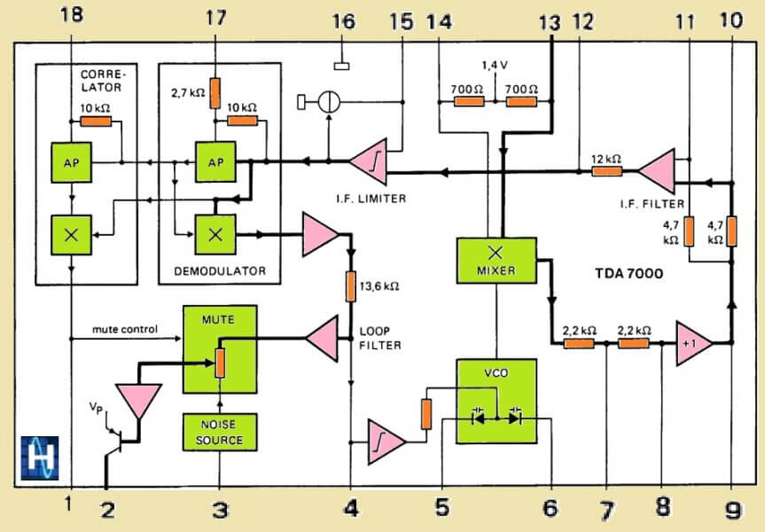
How the FM Radio Works:
Ok now after knowing the pin functions, let us understand what happens inside the IC when we power it ON.
- First, the antenna catches the FM signals from the air.
- The RF signal enters the IC through pin 12.
- Inside the RF amplifier stage boosts the weak signal.
- Then the mixer stage mixes the RF signal with internal oscillator signal to produce an intermediate frequency (IF) signal.
- This IF signal is then passed through an internal ceramic filter.
- After filtering, then signal goes to the FM detector block, where it is demodulated and converted into audio signal.
- Finally the audio comes out from pin 2 which we can connect to a small amplifier or headphone.
PCB Layouts
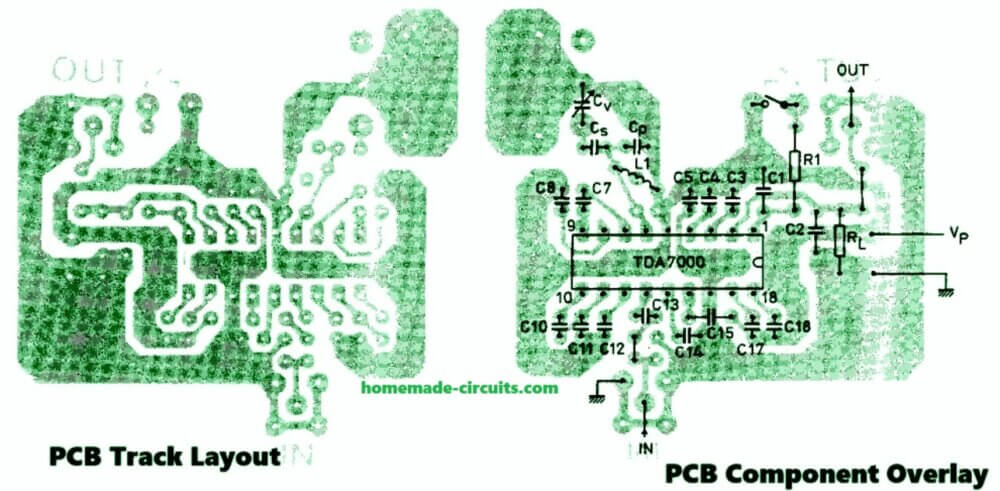
Simple Step-by-Step Construction:
- First fix the TDA7000 IC properly on the PCB.
- Start connecting all the capacitors and resistors as shown in the schematic. Use small ceramic capacitors.
- Connect a small coil (around 56nH) at pin 7 for tuning purpose.
- Connect a trimmer capacitor if you want to fine-tune your FM stations better.
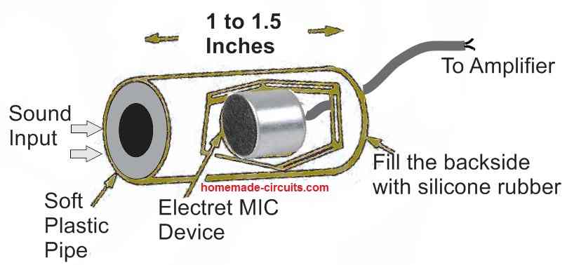
- Connect a small telescopic antenna or simple 75cm wire to the RF input pin 12.
- Connect the output pin 2 to a small audio amplifier (like LM386) or headphone directly.
- Supply +4.5V to +5V DC to pin 6.
- Ground pins 10 and 11 properly.
Once all connections are done, then just power ON and slowly adjust the trimmer capacitor to catch FM stations.
Important Tips:
Use short wires for capacitor and coil connections.
Keep the antenna wire away from noisy electronics.
Supply voltage should be very clean, better use a battery pack.
Tuning coil and trimmer should be properly adjusted to get maximum clear stations.
That's it!
Now your TDA7000 FM Radio is ready and blasting cool music from the air!
Parallel Capacitor Values around L1 (Tuned Tank Circuit)
So in the TDA7000 FM radio, the tank circuit is made by one coil (L1) and some capacitors around it.
This part is very very important because it decides which FM station range you will catch.
Here is the basic connection again (rough idea):
Between pin 6 (Vcc) and pin 7 (tank):
→ L1 (56nH) is connected in series.
→ Parallel to L1 we connect CP (tuning capacitor) and CW, CS capacitors.
Now about the capacitor values:
| Symbol | Rough Value | Purpose |
|---|---|---|
| CP (parallel cap) | 22 pF to 47 pF | Main tuning cap (with trimmer) |
| CW (fixed cap) | 10 pF to 22 pF | Frequency setting support |
| CS (fixed cap) | 10 pF to 22 pF | Frequency setting support |
| CD (parasitic cap) | Small around 2 pF to 5 pF | Fine adjusting |
Example Setup (for 88 MHz to 108 MHz FM Band):
L1: 56nH (small air core coil, around 2 or 3 turns, having 5mm diameter, using 22SWG magnet wire)
CP: 39pF trimmer or 47pF fixed capacitor
CW: 18pF
CS: 18pF
CD: 3pF
Note: If you use a trimmer for CP (like 10pF to 50pF adjustable) then you can nicely sweep across the full FM band.
L1 and CP mainly decide the resonance frequency, other caps (CW, CS) slightly help to fine adjust.
Super Simple Tip:
If you dont want to calculate too much then just do this:
Make L1 = 56nH (2 or 3 turns, 5mm dia)
Connect 33pF or 47pF across it (CP)
Put a 10pF cap in parallel (CW)
Then add a trimmer capacitor (10 to 30pF range) to fine tune.
This will easily catch almost all the FM stations from 88MHz to 108MHz.
Complete Parts List for TDA7000 FM Radio Receiver
| Sl. No. | Component | Value / Part Number | Quantity | Notes |
|---|---|---|---|---|
| 1 | IC | TDA7000 | 1 | Main FM radio IC |
| 2 | Capacitor (C1) | 4.7 µF / 16V (Electrolytic) | 1 | Audio coupling at output |
| 3 | Capacitor (C2) | 0.1 µF (104) Ceramic | 1 | Power supply decoupling |
| 4 | Capacitor (C3) | 10 µF / 16V (Electrolytic) | 1 | Audio filter / gain stage |
| 5 | Capacitors (C4, C5) | 10 pF to 22 pF Ceramic | 2 | De-emphasis or detector filter |
| 6 | Capacitor (CP) | 33 pF to 47 pF Ceramic | 1 | Tuning tank capacitor (parallel) |
| 7 | Capacitor (CW) | 10 pF to 22 pF Ceramic | 1 | Tank support |
| 8 | Capacitor (CS) | 10 pF to 22 pF Ceramic | 1 | Tank support |
| 9 | Capacitor (CT) | 10–30 pF Trimmer | 1 | For FM fine tuning |
| 10 | Capacitor (C6) | 1 nF (102) Ceramic | 1 | RF decoupling |
| 11 | Coil (L1) | 56nH (2–3 turns, 5mm dia) | 1 | Main tank inductor |
| 12 | Resistor (R1) | 10k | 1 | Mute pull-up |
| 13 | Resistor (R2) | 100 ohm to 1k | 1 | Audio load matching |
| 14 | Antenna | 75cm wire or telescopic | 1 | Simple FM antenna |
| 15 | Audio Amplifier | LM386 / Any small amp | 1 | To hear loud audio |
| 16 | Speaker or Earphone | 8 ohm / 32 ohm | 1 | Output device |
| 17 | Power Supply | 4.5V or 5V DC (battery) | 1 | Clean regulated DC |
How to Integrate IC TDA7000 to an Amplifier Circuit
If you want to hear the FM sound from the above explained TDA7000 IC based FM radio then you will need to integrate an amplifier circuit with this IC, which can drive a small 8 ohms loud speaker.
As shown in the following figure, we can use an LM386 amplifier IC for enabling the FM audio to be heard through a loud speaker. The complete circuit diagram of a TDA7000 FM radio with amplifier circuit is shown in the following figure:
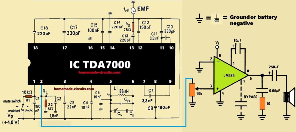
As can be seen, the FM audio output from pin#2 of the TDA7000 is connected with the pin#3 of the LM386 amplifier IC, through a 10k potentiometer which acts like a volume control.
Extra Notes:
- All ceramic capacitors should be disc type for improved stability.
- You can use a small 5V battery pack (3 x 1.5V cells) for clean and noise-free supply.
- Use a socket for the TDA7000 IC if possible, so it is safe during soldering.
- If you get buzzing or poor audio then just try adding a 100 µF capacitor near Vcc for extra smoothing.
Sources:


Comments
PCB siparişi vermek istiyorum.