In this article I have explained a remote controlled wireless home security circuit using which enables the detection of a possible intrusion way in advance depending on how and where the remote sensors are positioned over the selected strategic locations and the desired distance from the house. The idea was requested by Mr. Dave Monette.
The request is in the form of an email discussion between Mr. Dave and me, as presented below:
Technical Specifications
My son and I thought of a very useful project to work on. I am a mechanical engineer but have dabbled in electrical circuits for some time now.
The wireless home security circuit project could have many applications but for us would be for deer hunting season. Often times the deer seem to sneak up on us without warning but they almost always use one of several worn paths. The goal would be to get some advance warning before they arrive.
I was thinking to mount some sort of PIR circuit (must be self powered because no line power in the woods) to a tree along each of the 4 or 5 main paths the deer will travel. Once the PIR is tripped by the deer it would have to send some sort of signal to the blind we sit in.
I was thinking of a box with five LEDs labeled "path 1", "path 2", etc. The signal would have to have very little delay. Ideally the signal would be able to be transmitted up to 200 yards, although if the range were less it would still be helpful.
When the light on the board/box lights up, it would be nice if it would be accompanied by an low audible tone (not very loud so it wouldn't scare the deer) also, the light should remain on (read delay) for 15-60 sec after in turns on (so we don't miss the light if a deer quickly trips the PIR while moving quickly down the trail.
What do you think? We have been discussing this project for almost a year now but I have not reached out to any experts and it is well outside of my electrical/electronics capability.
Dave Monette (and 15 yr old son Collin)
P.s. I love your www.www.homemade-circuits.com site. I have learned so much from reading it and studying the circuits. Circuit design really interests me.
Analyzing the Circuit Request
Thank You Dear Dave, I appreciate your thoughts very much!
Your write-up is so good, I wish I could use it as a new article for my site
However unknowingly you have said something that's extremely sensitive and hurting to me, so pardon me I won't be able to help you with this project since it's connected with animal cruelty.
Swag,
Sorry if I offended you with regard to hunting but as I stated I can think of so many uses for a real time device like this. We live on a large piece of wooded property with several trails leading from the outside of the property to the house. Having a device like this would serve as early warning for personal protection.
One more thing Swag, we live in Michigan and we lead the nation (by far actually) in traffic fatalities involving deer / vehicle encounters.
If people did not hunt in Michigan there would be 100's of lives lost every year due to the overpopulation of deer alone.
Even with all of the people that hunt in Michigan (last year there were over 500k deer taken during hunting season) the deer population is on the rise. Deer are reproducing faster than available food sources in Michigan.
Last year alone, over 25,000 deer were found dead from starvation or malnutrition.
Hopefully you can see it in your heart to help us on this project.
I told me son what a wizard you are and we even studied some of your circuits together. Like I stated earlier, there are many uses for such a device outside of hunting.
Hope to hear from you soon Swag. Thanks for writing me back, Dave M.
Reply:
I understand Dave, still either way it's a painful death for the poor animal. Instead of controlling by killing, wouldn't it be better to employ a birth control strategy to minimize their population?
Anyway, I'll try to figure it out and imagine it to be for some other application need...as you said, the design could be used as a warning device also.
I'll design it and let you know soon. I truly appreciate Collin's and your views regarding my site, thanks so much!
Thank you Swag. I talked with a guy at my work (Chrysler) and explained the concept to him. Immediately, he said "that would be perfect for home security".
He lives on 40 acres and would to know cars or trucks pass any of his 5 bridge / driveways onto his property. The farthest bridge from his home is about 0.25 mi (approx 1300 feet).
Currently, he has trail cameras set up at each driveway but that does nothing to tell him of the presence of a truck on his property in real time.
He said the ground between his house and the farthest driveway is mostly flat and moderately wooded.
He says you cannot see the farthest bridge from his house looking through the trees.
My son and I are both super excited to work with you on this project.
Dave
The Design
The proposed remote controlled solar wireless home security circuit can be understood with the help of the following explanation:
In one of my earlier articles I explained regarding a simple yet foolproof proximity sensor or motion detector which employed infrared signals to spot and reflect an intruder's presence within the zone, and trigger an alarm.
The design may be learned comprehensively in the following article:
Simple Proximity Detector Circuit
The same concept has been used in the present home security system, owing to its simplicity, better accuracy and cost effectiveness compared to a PIR counterpart.
In this design instead of PIR sensors, ordinary infrared photodiodes are employed, as may be seen in the diagram below:
The Schematic
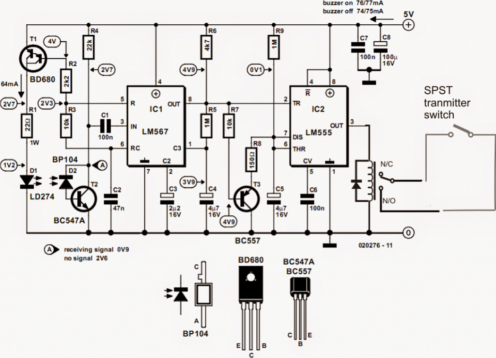
How the Diodes Work
In the design, D1 and D2 form the IR transmitter and the Receiver devices respectively and are positioned somewhat parallel with each other or with a certain angle, and pointing towards the zone which needs to be monitored.
D1 is allowed to produce a continuous oscillating IR signal focused towards the restricted zone, and if an intruder tried to pass across this zone the transmitted signal is expected to hit the intruder and get reflected towards D2, which is instantly captured by D2 for further precessing.
Why LM567 is Used
Here the IC LM567 is configured as a tuned IR transmitter/receiver stage which becomes responsible of generating IR signal via D1 at a given frequency, determined by R3/C2, through pin#5.
The above condition also enables the IC to become exclusively responsive towards this frequency across its pin#3 and reject any possible stray signal of a different frequency.
When the reflected IR signal is detected by D2, the frequency is immediately recognized by pin#3 of the IC and processed internally such that pin#8 of the IC is rendered low in response to the detection.
However, the above situation is sustained only as long as the IR rays keep reflecting from the intruder body and is inhibited the moment the intruder gets away.
In order to introduce a delay to the above process regardless of the detection time, an IC 555 monostable stage can be seen integrated with pin#8 of the IC LM567.
The Role of IC 555
As soon as a low is sent at pin#8 of the IC LM567, the IC 555 is instantly triggered causing its pin#3 to go high and remain latched for some predetermined period, as determined by the values of R9/C5.
Pin#3 of the IC555 can be seen connected with a relay which is expected to toggle in this situation and stay activated for the calculated period of delay.
For security system which does not require a remote controlled operation, a siren or alarm can be wired across the shown relay contacts for the final outcome.
Using a Remote Control Module
However, since in our application a remote controlled home security circuit is intended, we use the relay activation to toggle an RF transmitter stage as I have explained below:
Today, readymade RF transmitter, receiver modules are pretty commonly available in the market and can be procured for the discussed application.
The modules are available in the form of open assembled PCB boards, I have already explained a related post in this website, you may have a glimpse of it in the following post:
Simple RF car security circuit
The PCBs needs to be appropriately wired as explained in the article for implementing the purpose.
One can choose to build the above circuits and attach one of the transmitter switches with the relay contacts associated with the above IR circuit's IC 555 stage.
Or if the assembly looks tough, one may simply buy a set of neatly assembled ready made unit as shown below:

How the Tx and Rx Modules Work
As may be seen in the above image, the readymade Tx, Rx modules would be available in the above shapes.
The right side is the Tx or the transmitter handset, which we need to open and integrate the two solder points of the micro-switch, under the red button with the relay contacts of our IC 555 stage.
The module could be possibly powered with a 3V button cell which would need to be removed and the +/- terminals appropriately connected with a 3V regulated DC source.
The left side module with the blue relay is the Rx or the receiver module which is supposed to receive the transmitted signals from the Tx module and toggle the blue relay accordingly.
This unit is supposed to be installed at the base station or the home which needs to be informed regarding a possible intrusion, while the Tx circuit along with the IR detector together needs to be hooked up over a tree or the near the restricted location and appropriately focused across the zone.
How to Wire the Remote Control Modules
The wiring details of the Rx unit may be learned as given in the following image:
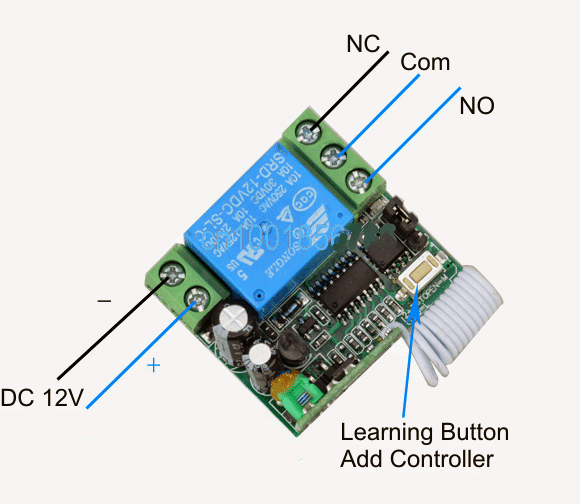
The relay contacts of the Rx unit as indicated in the above image may be appropriately wired with an audible alarm system or any other desired form of recordable alarm system.
In the above discussion we understood the details regarding the building and installing of the proposed remote controlled home security circuit system, now it's time to identify how the Tx may be powered through a solar rechargeable battery circuit.
How to Build the Solar Powered DC UPS
The following image tells us regarding how simply a solar powered 5V uninterruptible supply may be achieved using a small solar panel and a 7805 voltage IC.
Solar 5V Battery charger circuit for the above wireless home security circuit
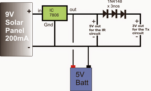
The above 5V solar battery charger circuit may be used for powering the remote detector transmitter assembly, the whole system along with the panel and the circuits may be positioned over a tree or some kind reinforced steel structure on the ground, and camouflaged appropriately.
This concludes the article regarding a cheap yet effective home security circuit which enables the user to detect an intrusion in advance, which may take place far away across the lanes or passages finally leading to the user's house.
The article details only one such module, although many such self contained remote IR modules may be built and installed across zig-zag lanes, enabling multiple tracking and detection for the target.
Feedback from Mr. Dave
Wow Swag, I am so impressed. I have a few simple questions:
1. What type of range could be expected with the simple push button style tx and rx
module pair shown in the picture? (Maybe 100m max??)
2. What would/could you use if the requirement was say 1000m? (I see guys flying FPV
drones or planes over 5000m online)
3. How expensive might a tx/rx module pair capable of 1000m be? Can you suggest a
model or location to buy?
4. Several spots on your schematic you have labels like "4V9", I thinking this must
mean 4.9V when using a 5.0V battery. Am I reading the schematic right??
Thanks so much. Now I need to order the parts and get building.
Thank you Dave =)
Here are the answers:
1) Yes the range is around 100 meters for the specified Tx, Rx modules
2) There are a few long range options available online, there's one that uses the IC PT2262 and is assigned to provide a good 2km range, the datasheet of the device may be studied in the following link:
https://pdf.datasheetcatalog.com/datasheet/PrincetonTechnologyCorporation/mXusxsq.pdf
However the relay stage is not included in the module which you may have
to associate for the required actions. It can be simply done by
integrating a relay driver stage with the "OUT" pin of the Rx module.
3) The indicated cost appears to be around $18.....
4) yes you are reading the schematic absolutely correctly:)
By the way if you prefer to use a PIR circuit, you may switch to the
following design.
https://www.homemade-circuits.com/2014/09/automatic-pir-controlled-fan-circuit.html
Best Regards
Swag
In case a PIR is preferred instead of the discussed IC 567 tuned IR design, the same may be achieved by integrating the PIR system with the RF modules as shown in the following diagram:
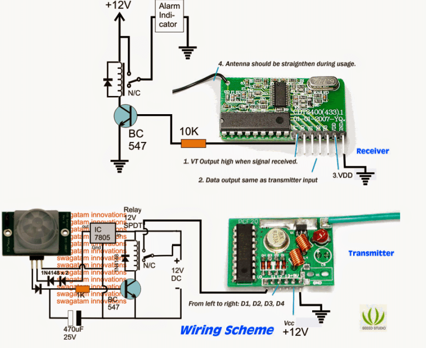
The above wireless home security circuit is self explanatory, the relevant components simply needs to be wired as per the given instructions in the above diagram.
If you have doubts or confusions please feel free to comment below:


Need Help? Please Leave a Comment! We value your input—Kindly keep it relevant to the above topic!