In this project we are going to control a manual robot through our cellphone using DTMF module and Arduino.
By: Ankit Negi, Kanishk Godiyal and Navneet Singh sajwan
INTRODUCTION
In this project two cell phones, one for calling and one for receiving the call are used. The phone receiving the call is connected to the robot via audio jack.
The person who is calling can control the robot just by pressing the dial pad keys. (i.e. the robot can be operated from any corner of the world).
COMPONENTS REQUIRED
1 - Arduino UNO
2 – Manual robot
3 - 4 motors (here we used 300 r.p.m each)
4 - DTMF module
5 - Motor driver
6 – 12 volt Battery
7 - Switch
8 - Headphone Jack
9 – Two Cell Phones
10 – Connecting wires
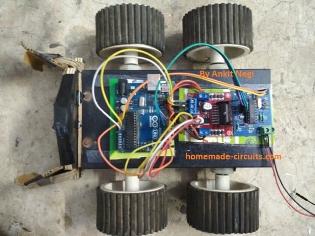
ABOUT MANUAL ROBOT
A manual robot consists of chassis (body) in which three or four motors (which are screwed with tyres) can be attached depending on requirement.
Motors to be used depend on our requirement i.e. they can either provide high speed or high torque or a good combination of both. Applications like quad copter requires very high speed motors to lift against gravity while application like moving a mechanical arm or climbing a steep slope requires high torque motors.
Both motors on left and right side of robot are connected in parallel separately. Usually they are connected to a 12volt battery via DPDT(double pin double throw) switches.
But in this project we will use mobile phone instead of DPDTs to control the bot.
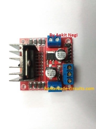
ABOUT MOTOR DRIVER
Arduino gives maximum current of 40mA using GPIO (general purpose input output) pins, while it gives 200mA using Vcc and ground.
Motors require large current to operate. We can’t use arduino directly to power our motors so we use a motor driver.
Motor driver contains H Bridge (which is a combination of transistors). The IC (L298) of motor driver is driven by 5v which is supplied by arduino.
To power the motors, it takes 12v input from arduino which is ultimately supplied by a 12 v battery. So the arduino just takes power from battery and gives to the motor driver.
It allows us to control the speed and direction of motors by giving maximum current of 2 amperes.
INTRODUCTION TO DTMF MODULE
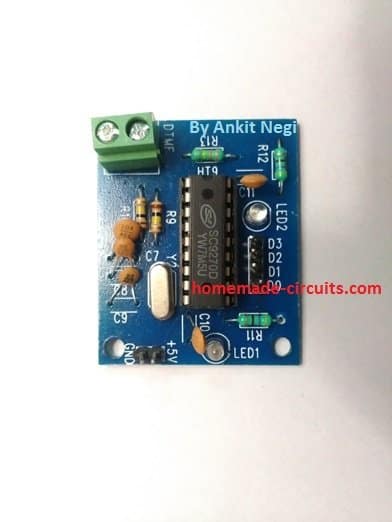
DTMF stands for Dual tone multi frequency. Our dial pad is a two toner multiple frequency i.e. one button gives a mixture of two tones having different frequency.
One tone is generated from a high frequency group of tones while other from a low frequency group. It is done so that any type of voice can’t imitate the tones.
So, it simply decodes the phone keypad’s input into four bit binary code. The frequencies of keypad numbers which we have used in our project is shown in the table below
DigitLow frequency(hertz)High frequency(hertz)2697133647701209677014778852133609411336
The binary decoded sequence of the dial pad’s digits is shown in the table below.
digitD3D2D1D010001200103001140100501016011070111810009100101010*1011#1100
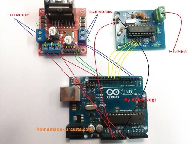
CIRCUIT DIAGRAM
CONNECTIONS
Motor driver –
- Pin ‘A’ and ‘B’ controls left side motor while Pin ‘C’ and ‘D’ controls right side of motor. These four pins are connected to the four motors.
- Pin ‘E’ is to power IC(L298) which is taken from arduino (5v).
- pin ‘F’ is ground.
- Pin ‘G’ takes 12 volt power from battery via Vin pin of arduino.
- Pins ‘H’, ‘I’, ‘J’ and ‘K’ receives logic from arduino.
DTMF –
- pin ‘a’ is connected to 3.5 volt of arduino to power the IC (SC9270D).
- Pin ‘b’ is connected to ground.
- The input of DTMF is taken from phone via jack.
- The output in the form of binary data via (D0 – D3) pins goes to arduino.
ARDUINO –
- the output of DTMF from (D0 – D3) pins comes to digital pins of arduino. We can connect this output to any of the four digital pins varying from (2 – 13) in arduino. Here we used pins 8, 9, 10 and 11.
- Digital pins 2 and 3 of arduino are connected to pin number ‘H’ and ‘I’ of motor driver while pins 12 and 13 of arduino are connected to ‘J’ and ’K’.
- The arduino is connected to a 12 volt battery.
Program CODE-
int x, y, z, w;
int a = 0;

void setup() {
  pinMode(2, OUTPUT);
  pinMode(3, OUTPUT);
  pinMode(12, OUTPUT);
  pinMode(13, OUTPUT);

  pinMode(8, INPUT);
  pinMode(9, INPUT);
  pinMode(10, INPUT);
  pinMode(11, INPUT);

  Serial.begin(9600);
}

void reading() {
  x = digitalRead(8);
  y = digitalRead(9);
  z = digitalRead(10);
  w = digitalRead(11);
}

void decoding() {
  if(x==0 && y==0 && z==0 && w==0) a = 0;
  else if(x==0 && y==0 && z==1 && w==0) a = 2;
  else if(x==0 && y==1 && z==0 && w==0) a = 4;
  else if(x==0 && y==1 && z==1 && w==0) a = 6;
  else if(x==1 && y==0 && z==0 && w==0) a = 8;
  else a = 99; // unknown code
}

void move_forward() {
  digitalWrite(2, HIGH);
  digitalWrite(3, LOW);
  digitalWrite(12, HIGH);
  digitalWrite(13, LOW);
}

void move_backward() {
  digitalWrite(3, HIGH);
  digitalWrite(2, LOW);
  digitalWrite(13, HIGH);
  digitalWrite(12, LOW);
}

void move_left() {
  digitalWrite(2, HIGH);
  digitalWrite(3, LOW);
  digitalWrite(12, LOW);
  digitalWrite(13, HIGH);
}

void move_right() {
  digitalWrite(2, LOW);
  digitalWrite(3, HIGH);
  digitalWrite(12, HIGH);
  digitalWrite(13, LOW);
}

void halt() {
  digitalWrite(2, LOW);
  digitalWrite(3, LOW);
  digitalWrite(12, LOW);
  digitalWrite(13, LOW);
}

void loop() {
  reading();
  decoding();

  if(a == 2)       move_forward();
  else if(a == 8)  move_backward();
  else if(a == 4)  move_left();
  else if(a == 6)  move_right();
  else             halt();

  Serial.print("x="); Serial.print(x);
  Serial.print(" y="); Serial.print(y);
  Serial.print(" z="); Serial.print(z);
  Serial.print(" w="); Serial.print(w);
  Serial.print(" a="); Serial.println(a);

  delay(50);
}
Code Explanation
Now we start this whole thing by telling that we first keep some variables at the top and we let Arduino use these variables everywhere inside the program.
We keep x, y, z, w for reading the DTMF bits, and we keep a for holding the final decimal value after decoding.
Setup Explanation
Now when we enter inside void setup, then we tell Arduino which pins are INPUT and which pins are OUTPUT. So we set pin 8, pin 9, pin 10 and pin 11 as INPUT because DTMF module sends digital bits on these pins.
And we set pin 2, pin 3, pin 12 and pin 13 as OUTPUT because we want to run the left motor and right motor from these pins. After that we start Serial.begin so that you and me can see the readings in Serial Monitor.
Reading Function
Now we make a small function called reading. In this reading function we simply tell Arduino that it must collect the digital HIGH and LOW values from pin 8, pin 9, pin 10 and pin 11 and put them inside x, y, z and w. So we know always what binary code is coming from phone keypad.
Decoding Function
Now we make another function called decoding. In this decoding function we take that x, y, z, w and we decode that into one decimal number.
So when x y z w become 0010 then we make a = 2 and when they become 0100 then we make a = 4 and same way we take few more patterns.
We also put one a = 99 so that if then the pattern is not known then Arduino understands that nothing must move.
Movement Functions
Now we create five functions because the robot has to move in different ways. So we make move_forward, move_backward, move_left, move_right and halt.
In these functions we tell which pin must go HIGH and which pin must go LOW so that the left tyre and right tyre behave in correct direction.
So now every time Arduino calls one of these functions then the robot behaves exactly how we want.
Main Loop Explanation
Now when we enter the main loop, then the first thing we do is that we call reading so that Arduino knows what DTMF code is coming now.
Then we call decoding so that Arduino converts that binary pattern into a decimal value stored in a.
After that we check a by using if and else if. So when a equals 2 then Arduino calls move_forward. When a equals 8 then Arduino calls move_backward.
When a equals 4 then Arduino calls move_left.
When a equals 6 then Arduino calls move_right.
And when the value does not match anything then Arduino calls halt so that the robot does not move anywhere.
So now everything depends on a and we do not check x, y, z, w again and again.
Printing Function
Now we also print x, y, z, w and a so that you can see in Serial Monitor what value is coming from DTMF and what value Arduino is decoding.
So this helps us in debugging also when then some key does not work properly.
Complete Working
So now when you press any button on your phone then the DTMF module sends one 4 bit code to Arduino pins.
Then Arduino reads that, decodes that and changes the value of a. Then Arduino compares a and calls one movement function. Then the robot moves exactly based on that value.
So everything becomes straight and simple because now we use the final decoded value a instead of checking raw binary pins again and again.
CIRCUIT WORKING
The controls which we have used in our project are as follows –
2 – To move forward
4 – To turn left
6 – To turn right
8 – To move backwards
0 – to stop
After making a call to the phone connected to the robot, the person opens his dial pad.
- If ‘2’ is pressed. The DTMF receives the input, decodes it in its binary equivalent number i.e. ‘0010’ and sends it to digital pins of arduino. The arduino then sends this code to the motor driver as we have programmed when the code will be ’0010’, the motors will rotate in clockwise direction and hence our robot will move forward.
- If ‘4’ is pressed then its equivalent code is ‘0100’ and according to the programming the left side motors will stop and only right side motors will rotate clockwise and hence our robot will turn left.
- If ‘6’ is pressed then the right side motor will stop and only left side motors will rotate clockwise and hence our robot will turn right.
- If ‘8’ is pressed then our motors will rotate in anticlockwise direction and thus our robot will move backward.
- If ‘0’ is pressed then all our motors will stop and robot will not move.
In this project we have assigned a function to five dial pad numbers only. We can add any type of other mechanism and assign a dial pad number to that mechanism to make an upgraded version of this project.
POINTS TO KEEP IN MIND
1 – The jack should not be loose.
2 – Phone keypad tones should be maximum.
3 – Internet/ Wi-Fi of receiving phone should be closed to avoid interference effects.
4 – Left pin (i.e. pin ‘b’) of DTMF is ground and right pin (i.e. pin ‘a’) is connected to 3.3v.
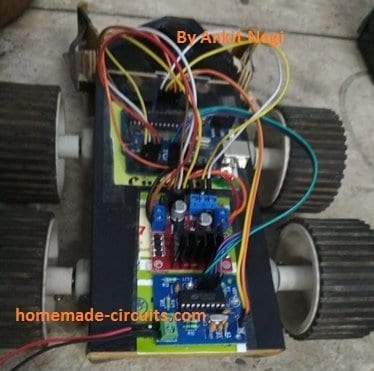
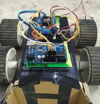
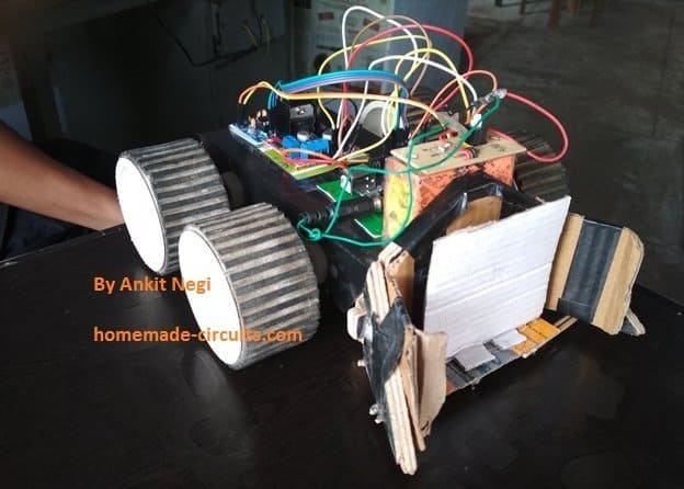
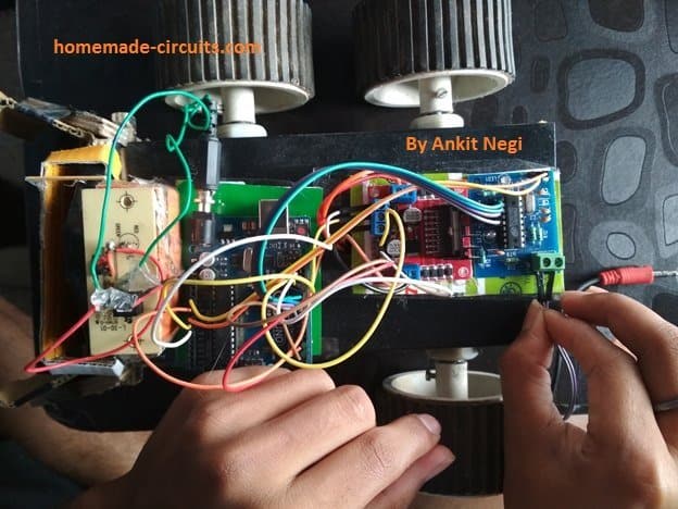
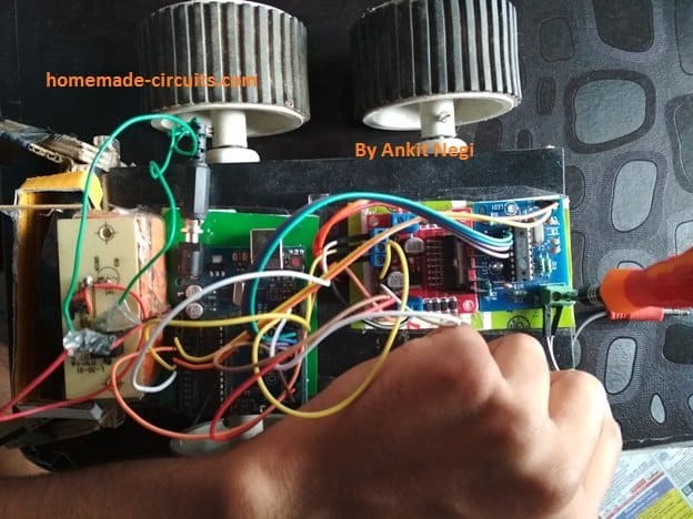
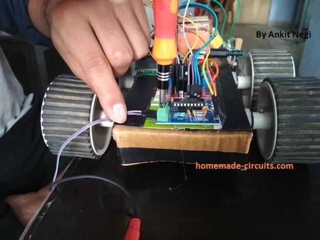
Prototype images of the cellphone controlled robot car circuit using DTMF


Questions & Answers
Does this comes under IOT?
what’s gonna be the total cost of this project?
Rs.1500/- approx