We all are pretty familiar with the 78XX voltage regulator ICs or the adjustable types such as LM317, LM338 etc. Though these regulators are outstanding with their specified functioning and reliability, these regulators have one big disadvantage.... they won't control anything above 35V.
Circuit Operation
The circuit presented in the following article introduces a DC regulator design which effectively counters the above issue and is able handle voltages as high as 100V.
I am a great admirer of the above mentioned types of ICs simply because they are easy to understand easy to configure and require bare minimum number of components, and are also relatively cheap to build.
However in areas where input voltages can be higher than 35 or 40 volts, things become difficult with these ICs.
While designing a solar controller for panels which produces in excess of 40 volts, I searched a lot over the net for some circuit that would control the 40+ volts from the panel to the desired output levels, say to 14V, but was quite disappointed as I couldn't find a single circuit which could fulfill the required specifications.
All I could find was a 2N3055 regulator circuit which couldn't supply even 1 amp current.
Failing to find a suitable match I had to advise the customer to go for a panel that would not generate anything above 30 volts...that's the compromise the customer had to make using a LM338 charger regulator.
However after some thinking I could finally come up with a design which is able to tackle high input voltages (DC) and is a lot better than the LM338/LM317 counterparts.
Let's try to understand my design in details with the following points:
Referring to the circuit diagram, the IC 741 becomes the heart of the entire regulator circuit.
Basically it has been set up as a comparator.
Pin#2 is provided with t a fixed reference voltage, decided by the value of the zener diode.
Pin#3 is clamped with a potential divider network which is appropriately calculated for sensing the voltages exceeding the specified output limit of the circuit.
Initially when the power is switched ON, R1 triggers the power transistor which tries to transfer the voltage at its source (input voltage) across the other side of its drain pin.
The moment voltage hits the Rb/Rc network, it senses the rising voltage conditions and within a fraction of a second the situation triggers the IC whose output instantaneously goes high, switching off the power transistor.
This instantly tends to switch OFF the voltage at the output reducing the voltage across Rb/Rc, prompting the IC output to go low again, turning ON the power trasistor so that the cycle locks in and repeats, initiating an output level that's just exactly equal to the desired value set by the user.
Circuit Diagram
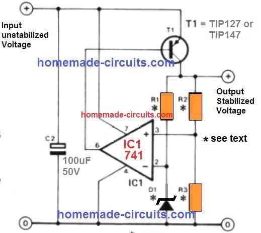
The values of the unspecified components in the circuit may be calculated by the following formulas and the desired output voltages may be fixed and set up:
R1 = 0.2 x R2 (k Ohms)
R2 = (Output V - D1 voltage) x 1k Ohm
R3 = D1 voltage x 1k Ohm.
The power transistor is a PNP, should be suitably selected which can handle the required high voltage, high current in order to regulate and convert the input source to desired levels.
You can also try replacing the power transistor with a P-channel MOSFET for even higher power output.
The maximum output voltage should not be set above 20 volts if a 741 IC is used. With 1/4 IC 324, the maximum output voltage can be exceeded up to 30 volts.
High Current Regulator with Low Dissipation
Power supply have been taken for granted since the introduction of the now-famous three-pin voltage regulators. However, there are times when such a regulator is insufficient. This sort of regulator requires a significant potential drop across it (usually greater than 3 V) and a high quiescent current (typically 6 mA for a 78xx). The regulator shown here is very appealing for battery-operated devices, as it provides:
- The output voltage is variable and highly steady.
- Reduced potential drop (some tenths of a volt).
- Quiescent current of a very small magnitude (20-30 uA).
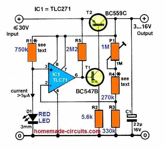
The regulator is a typical series type in theory. A common or garden red LED with a current demand of not less than 5uA is used as a voltage reference. An LED has a rather constant voltage drop at this modest current. The current is taken from the regulated output through R1. This improves the stability.
The TLC271 CMOS opamp provides regulation. By connecting pin 8 to the positive output terminal, this amplifier runs in the low bias mode, which assures extremely low current usage. The opamp's output is utilized as the basis drive for series regulator T2, which is driven by current source T1. This arrangement allows for good control of a tiny voltage swing at the opamp's output.
This is important because the opamp's slew rate in low-bias mode is rather low. The opamp gets its power from the regulator output as well. Capacitor C1 acts as a decoupling element for the opamp as a result. A type of bootstrap resistor, R5, was determined to be required for efficient control.
The settings of R1 and R4 in the diagram result in a 3 to 8 V adjustable output voltage. R4 can be increased by 200 k / V to get higher output voltages of up to 16 V. As long as the current through D1 does not decrease under 5uA, the value of resistor R1 must be raised as well.
Long connections in this sort of circuit should be avoided at all costs to avoid parasitic capacitances. The regulation would deteriorate as a result of this. The peak output current is primarily determined by the allowable dissipation in T2 and, to a minor extent, by the voltage difference between the input and output.

Comments
Love the web page and thank you for having it up. I’m looking at the repair of an oil sensor CDI unit that has shorted out. It’s not easy to get into as the resin is rock hard. I managed to get to the mosfet pins by grinding with a mini grinder. For a short while I imagined to be a dentist :-). Exposing the 3 pins the multimeter showed a full short across all pins. My immediate thought was the mosfet to be faulty. Once removed, like a dentist pulling a tooth the circuit still shows a full short. It’s all a hobby thing to keep an old engineer busy. Thanks again for being there.
Glad you liked the page, however, I am not sure about the fault, it can be quite difficult to assess the fault without practically checking the unit and testing with a meter.
Hello Sir, with regards to the above circuit, Can you assist me with a circuit with output of 0-50vdc / and 0-40 amps regulatable, both voltage and current?
Chris, the above circuits do not have a current control feature. You can instead try upgrading the following circuit to get the required results:
https://www.homemade-circuits.com/wp-content/uploads/2021/01/Bench-power-supply-compressed.jpg
Thanks sir
Is this your own email ID? somebody has complained that you are using his email ID. I have provided your IP address to that person for further actions.
Thanks for the explanation. can you suggest alternate / custom circuit for the IXCY10M90S ( High voltage current regulator)?
I referred to the datasheet of the IXCY10M90S but could not find any useful information regarding how these are ICs configured to work. Let me investigate more if possible I will try to fulfill your request.
Hi Swagatam,
Thank you for your prompt reply. Thank you for the education. I will think a little more on my circuit design, as I am trying to limit waste of energy in the loss of heat (like a zener) and such?
Thank you for your time.
Richard ARGG
No problem Richard, I wish you succeed with the project.
Hi Swagatam,
I’ve hit a few snags with getting bits together to build the circuits and have also been thinking of different ways of achieving my aims.
I don’t understand something and no matter how much I look and read, I can’t find the answer. Are you able to educate me?
I don’t understand what components dictate/set an input voltage? I ultimately want to have an input voltage between 25VDC and 75VDC with an input capable of an amperage between 8A – 16A input?
Your first circuit above “High Voltage, High Current DC Regulator Circuit” simply says “Input, Un-stabilised Voltage” That’s what I want, un-stabilised from 25VDC to 75VDC, but I don’t understand what/how/which components set/accept this range?
Your next circuit “High Current Regulator with Low Dissipation” has an input of less than or equal to 30VDC, but I don’t get which components set this?
I understand the rest of the circuits and how they work, I can change/modify all the parts of the circuits and the outputs and I understand what is happening and why?
I just don’t understand what components set/dictate the input volts?
Are you able to educate me, point me towards documents that will help me to understand?
Thank you for your time
Richard ARGG
Hi Richard,
Since the ICs have certain voltage tolerances, the input voltage can’t go above those ranges. For example if we use LM358 op amp, it has a maximum tolerance capacity of 30 V, that means the maximum input DC cannot be exceeded beyond this voltage level.
That said, there maybe a workaround, in order to enable the use of higher voltages upto 75V. We can use a zener/resistor combination to restrict the op amp Vcc to 30V by using a 30V zener diode and a 10K resistor.
Once this is done, we can then tweak the relevant voltage adjustment potential dividers to get any variable output as desired up to 75 V.
Hi Swagatam. I agree with you, trying to find a DC/DC converter with an input voltage greater than 50VDC is difficult. I have not been able to find one, which is why your “High Current Regulator with Low Dissipation” interests me! A friend gave me his old solar panels when he upgraded. The spec’s on the panels say 58.6VDC & 470W out. In monitoring, I’ve found 61.6VDC to 70.4VDC & a maximum of 489W out, working very well? I would prefer a “Buck Converter”, but again, they don’t seem to go greater than 60VDC input?
Your circuit indicates greater than or equal to 30VDC input? Is that correct and what part of the circuit sets that up? What is the wattage rating of the resisters? Also, you state that R1 & R4 (and I suspect P1) are responsible for setting the output voltage? What is the formula to make the output in the range of 24VDC?
Love what you are doing, and thank you for your time.
Thank you Richard, I have a LM317 based buck converter but as you have mentioned, the maximum capacity is not beyond 60 V.
You can definitely customize the above two concepts to fulfill your requirement.
To make them work with over 60 V (below 100V) inputs you may have to first ensure the op amp is protected from the high voltage, which can be done by connecting the VCC pin of the ICs through a 4k7 2 watt resistor, and adding a 12V zener across the VCC and the ground pin of the ICs.
Next you may have to replace the T2 transistor in the second diagram with a MOSFET IRF9540 or any similarly rated FET. Yes R1/R4 or P1/R4 can be adjusted to vary the output voltage appropriately. I can’t figure out the exact formula for the output voltage, but it looks like it be similar to the first concept.
Hi Swagatam, thank you for your prompt reply. I’ve had a quick lock at the things you’ve suggested, but won’t get a good chance to work things through until the weekend.
A couple of things though? I originally asked about the wattages of the resisters in the circuits?
Also, in the regulator circuit. If I am putting between 60-70VDC input, I would need to increase the voltage value of C2?
Thank you for your time again.
Richard ARGG
No problem Richard.
All the resistors are 1/4 watt. Whenever the wattage is not given, you can assume them to be 1/4 watt. Yes the capacitor voltages should be preferably 1.5 times higher than the supply input value. If it is higher it is still better.
Hi Swagatam,
Excellent, Thank you. It may take longer to get the bits together and build it. I’ll let you know how it goes and I’ll start looking at some of your other designs.
Thank you for your time.
That sounds great Richard, I appreciate your feedback!
On your diagram shown T1 as PNP transistor. OK. BC161.16 is really PNP. But BD241A is NPN. What is going on ?
Check it now.
Interesting article. I found it when searching for low voltage high current regulator. Planing on using high quality PC power supply (seasonic) to make LiFePo4 cell charger. (3.65v 100 A) Any ideas how to go about that? In my past I played with LM317 and 2N3055 transistors but that might not work.
Thank you,
Dalibor
Thank you, and glad you found the post useful….however the main question is that from where would you get the 100 Amp source? I will surely try to solve your query, once I know the source of the 100 amp current
Namaste Sir
Thanks for your valuable circuit & comments..can i make it variable dc power supply
Please Suggest
N K Pattnaik
Thank you Nishikant, you can make it variable by replacing R3 with a potentiometer
Thanks,
PC Power Supply. 12 Volt rail. They are capable delivering large amounts of power, quality ones at least. Think of SeaSonic PC power suppply.
OK, in that case, you can try replacing the transistor T1 with 4 P-channel MOSFETs in parallel. The mosfet can be any 50 amp or 75 amp p chanell mosfet such as this:
https://www.onsemi.com/pdf/datasheet/mtb50p03hdl-d.pdf
Thanks Sir
Really i appreciate your help to build this type of circuit thanks sir
You are welcome Nishikant!
Hello. Interesting article. Is there a circuit that can boost voltage from 0.5-1volt to at least 65-70 volts, while allowing high current to pass through?
Hello, you can try the joule thief concept, and modify for getting the desired output voltages:
3 Best Joule Thief Circuits
Thank you for the recommendation.
I have use for a ~50v@~35A regulated DC power supply and I found two potential candidates in a 48vdc and a 70vdc power supply, but both are unregulated, but do have output filtering caps. Disregarding the tolerance of the device I’m trying to power, would it be better to use the 48v power supply and build a regulating circuit that regulates the output to ~46vDC? Or get the 70v power supply, and regulate it down to ~50vDC? And what would the advantage or disadvantage be of each, especially the higher voltage being regulated down 20vDC; is there a lot of heat generated when your regulated voltage is ~30% lower than the input voltage?
If a buck converter circuit is used then the 70V option will be great, as the buck converter will convert the excess voltage into a proportionate amount of current. If a linear regulator is used then the 48V option would work better, due to the decreased input output differential and lower dissipation
Great, thanks for the advice!
Oke .. I will try .!
Konfirm .. I have tried to looking for these parts in my city today .. but its not easy to get it .. I’ ve got these ..
D1 = 12 volt/0,5w
R1 = 2,7 k
R2 = R3 = 14 k
C1 = 10 uf/35 v
IC = 741 N
T1 = BC 161 /10
.. Will you correct it ..
It is correct, just make sure to connect 2nos 1N4148 in series with base of T1, to prevent leakage voltage from the op amp.
cathodes will go to op amp side, anodes will go to base side.
pin6 ———-|<—–|<——-T1 base
Nice learn your invention .. I am an amateur in electronical .. Keep share .. Very much ,thank you !!
Thank you!
.. I need to know about part of this circuit .. If I take Z2 =12 Volt ,so Rc = 12 k.ohm
Rb =Rc .. = 12 k.ohm
Ra = 2,4 k.ohm ..
Is it right ..?
I have changed the schematic with a new one, since the previous schematic was not correct, please check it now, and do the calculations accordingly….
Oke .. What the one you mean ?? .. I need to know your update schematic exactly ..
Please check the article, the diagram is updated.
Hi Swagatam,
I am building an inverter, but need to lower the 127 rectified DC voltage to arround 100V that will enter a coil for wireless power transmission, with a power of arround 2000W. Does a regulator circuit is enough to handle that much power?
Hi Kevin , yes it is possible to use linear regulator for the mentioned purpose, however the pass transistor will need to be significantly upgraded to handle this massive power.
Do you think a IXFB110N60P3 would be enough? It says that @25°C can handle 1890. We are looking to not be heavy dependant on heat sinks in out design. Also, does all the components on the voltage regultaro circuit need to have the same power rating (2kW)?
Yes it looks good to me, may be 3 of these in parallel will allow relatively smaller heatsink.
Only the pass transistor needs to be rated at the load level, and also other elements that may be in series with this line, for example a diode, ….rest of the supporting parts can be normally rated.
Thank you Mr. Greg, you can try the concept explained in the following article for getting voltages in killovolts:
https://www.homemade-circuits.com/make-this-enhanced-capacitive-discharge/
or salvage a circuit from a mosquito bat and pulse it intermittently to save power.
However, I would recommend using a sound distraction method than electrocution. You could install intermittent noise generator which can disturb the rats and keep them away from the area. Rats are very sensitive to sounds and noises, and will flee quickly in response to a sound nearby.
Good afternoon Mr. Swagatam,
Thank you so much for the prompt response. I am a lover of animals and don’t want to torture any animal even rats, however I am having a problems with rats/mice eating my vegetable plants in my garden. I have watched them at night on my surveillance cameras. I have tried everything short of glue traps or poison. I want to get rid of the rats in the most humane way possible. I’ve seen rats suffer in a snap trap in some cases. What I want to do is supply enough voltage across the electrode strips to kill the rat instantaneously. I believe this is more humane than snap traps glue or poison. I hope you can understand.
The circuit you provided: Can you tell me what the final stepped up voltage is? I’m not sure 240 volts is sufficient to kill instantaneously. Also is VR/1 a potentiometer? I have researched commercial versions of electric rat trap that use 7000 volts. (your thoughts please). I am very aware of the dangers of high voltage and will be responsible in using it. I have built a fully enclosed enclosure 1′ x 1″ x 10″ with a small opening in the front to allow only rats or mice. I will enclose the power supply in an aluminum box to keep it weather proof. I saw a YouTube video that used a similar enclosure using a stun gun as the supply voltage. The only problem with that is with a stun gun you have to continuously hold down the switch to deliver the stun voltage.
I’m not sure how the user was able to get it to work, and they aren’t answering my request. I have also seen YouTube videos of the user using a 12 volt battery connected in parallel to a large start capacitor, but not quite sure how that works either.
I have seen a lot of YouTube videos of users simply torturing the rats. As disgusting as rats are and despite the diseases they carry and the fact that I don’t want them in my yard or home, I don’t advocate in their torture. I don’t want to see the rats/mice suffer, I just want them gone in the most humane way possible.
Thank you,
Hi Greg, the easiest way to get a lethal AC with a short circuit protection is to plug-in two wires into the mains socket with individual 1uF/400 capacitor connected in series with each of the wires. This will be enough to electrocute any small animal.
For a 12 V Dc system you can use the following circuit
https://www.homemade-circuits.com/simple-high-voltage-generator-circuit/
But electrocuting any animal is considered to be severe cruelty to animal, and is severely inhuman under any circumstances.