This Guitar Jammer circuit I have explained below enables you to jam out to your favorite songs from your cellphone or computer.
You can mix an external audio track with your guitar sound, then use headphones to listen to the blended result.
Imagine playing note-for-note copies of legendary guitarist's riffs and exchanging scorching pentatonics, "hammer-ons," and "pull-offs" with the best players. By Sudhir Roy.
You would be surprised by the outstanding "presence" obtained from such a basic design once you've turned on the circuit and experienced the sound.
The fact that the headphones cancel out background noise from the room is one of the causes of this.
As a result, the combined output covers you with music, giving the impression that the guitar track you are playing is actually from one of your favorite albums.
Circuit Description
The following figure displays the guitar Jammer circuit. A 9-volt battery, B1, serves as the circuit's power source, while S1 is the power button.
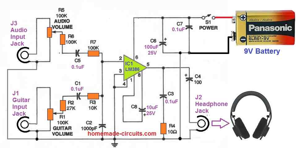
IC1 is an LM386 audio amplifier. Capacitors C6 and C7 are placed to provide decoupling for the IC1. With the shown configuration, IC1 has a gain of 200.
This much gain is perfect for this application and secure for your ears, thanks to the bypass capacitor C8, connecting pins 1 and 8!
J1, a common 3.5mm jack, receives the guitar input. Following that, the signal is routed to potentiometer R1 to adjust the volume.
The guitar signal leaves the wiper of R1 and travels via capacitor C1, resistors R2, and R3.
These resistors offer the best possible isolation between the external audio input and the guitar's volume control. As a result, the controls on the guitar only need minimal loading.
To avoid RF burst at the input, the guitar signal is therefore fed to pin 2 of IC1 and connected to shunt capacitor C2.
The jack J3 receives the audio input. Capacitor C5 serves as coupling, while potentiometer R5 is utilized to adjust volume.
Resistors R6 and R7 make sure that the guitar audio channel at pin 2 never switches to ground level.
The resultant mixed audio is produced at pin 5 of 1C1. This mixed audio is supplied into a standard Zobel shunt system built using R4 and C3.
At increased volume, this Zobel network keeps the audio output perfectly stabilized. Capacitor C4 is then used to transfer the finalized mono output to headphone connector J2.
Construction
Start by soldering an IC socket to your board. Then, connect the resistors and capacitors according to the layout.
Ensure short interconnections for better immunity.
For maximum noise isolation, twist the audio wires into one bundle. Shielded wire may also be employed for these connections, although it is not required.
After completing the board assembly, finally plug IC1 in the socket.
Now, install the audio jacks, switch, and potentiometers to a suitable enclosure having appropriate dimensions.
Make the necessary hookups across these components and the relevant connector terminals.
After that, connect a battery snap to the switch and the board's negative power line.
Using the Guitar Jammer
Verify the circuit's wiring with the diagram as you inspect it. Place a battery on the snapping if everything appears to be in order.
Plug your electric guitar to J1 using a regular guitar wire.
Next, attach a music input to J3 using the cable you built or purchased and connect J2 with your headphones.
Switch on the circuit and increase the volume on your guitar.
Strumming a chord with R1 at its minimum level, tweak the potentiometer until you obtain a pleasant loudness in the headphones.
Next, with your music input switched on, tweak the potentiometer, beginning with R5 at its minimum position.
Since the music signal would be larger than the guitar sound, you won't likely need to increase the volume all the way.
This concludes the testing procedure of the guitar jammer circuit.


Need Help? Please Leave a Comment! We value your input—Kindly keep it relevant to the above topic!