In this post I have explained how to use the control pin#5 of the IC 555 to build a simple PWM controlled DC light dimmer circuit.
The proposed DC lamp dimmer can be used for controlling the light intensity of any DC lamp having an operating voltage anywhere between 6 V and 12 V.
The lamp can be any 12V incandescent bulb or an LED bulb, upto 50 watts
How pin#5 of IC 555 can be used for PWM DC Lamp Dimming
The IC 555 is basically an 8 pin oscillator IC, but it can be configured for implementing various different circuit applications.
It can be configured as a monostable multivibrator circuit (one shot timer), an astable mutivibrator (ON/OFF oscillator), a PWM generator, a delay timer and many more.
The configuration which is used in our DC lamp dimmer circuit is a combination of an astable multivibrator and a variable PWM generator.
Fundamentally, assuming pin#5 is unconnected, the circuit works like an ordinary ON/OFF oscillator which continuously produces ON/OFF pulses at its output pin#3, at a specific frequency rate.
The frequency rate and width of these ON/OFF pulses is determined by the resistor/capacitor network connected across the pins#3, 2, 6, 7 of the IC 555.
However, as soon as the pin#5, which is the control pin of the IC, is rigged with a potentiometer, the circuit gets transformed into an adjustable PWM generator.
With this set up, the circuit's output ON/OFF pulses could be now adjusted to any desired mark/space ratio. Meaning the pulse width, or the ON/OFF duration of the output pulses could be now adjusted using this pot at its pin#5 to different levels, as desired.
When a MOSFET and a lamp are connected across the output, they respond to these varying PWM pulses and produce dimming or brightening effect on the lamp, depending on the pulse width adjustments.
How the Circuit Works
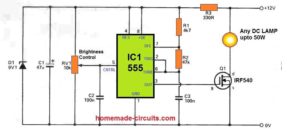
If you remove the potentiometer RV1 at the pin#5 of the IC 555 in the below shown circuit diagram, it simply becomes an ordinary astable multivibrator oscillator.
In this form it generates a continuous ON/OFF pulses at its output pin#3.
Resistor R1 along with capacitor decides the frequency of the ON/OFF pulses, whereas R2 decides the pulse width of the pulses. This also means that R2 to some extent can be also used for adjusting the output PWM, although R2 is a fixed resistor here.
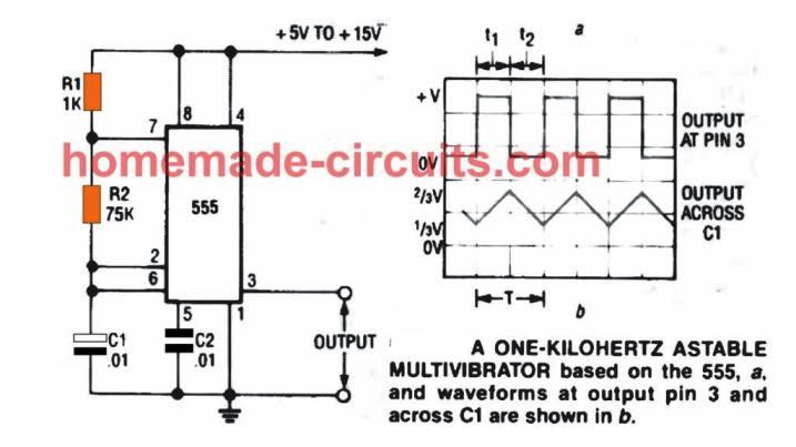
The following formulas can be used for calculating the output ON time and output OFF time of the pulses:
- TON ≈ 0.7(R1 + R2)C
- TOFF ≈ 0.7 R2C
How the Potentiometer at Pin#5 Works
As explained above as soon as we connect a potentiometer RV1 at the pin#5, it now quickly facilitates the adjustment of the PWM at the output pin#3 of the IC.
When the pot wiper is shifted towards the positive supply, it increases the potential on pin#5 of the IC Due to this the charging time of C2 is increased and discharge time is made faster, which causes the ON pulse to become wider and the OFF pulse to become shorter.
Exactly the opposite happens when the pot wiper is dragged towards the ground line of the supply.
Now the potential on the pin#5 decreases causing the ON time of the pulses to shrink, and the OFF time of the pulse increases.
How the MOSFET Executes the Dimming function on the Lamp
The MOSFET basically works like an ON/OFF switch here.
The MOSFET is switched rapidly with the PWM pulses from pin#3 at the gate of the MOSFET. Since the lamp is connected at the drain of the MOSFET, the lamp also switches ON/OFF rapidly.
However, due to the persistence of vision we end up seeing the lamp glowing continuously.
As the pulse width of the pin#3 varies, the switching rate of the MOSFET also varies.
How the PWM affects the Lamp Brightness
When RV1 is adjusted to generate PWMs with longer ON time and shorter OFF time, this causes the MOSFETs to produce longer switch ON periods, and shorter switch OFF periods on the lamp.
Again, due to persistence of vision, we do not see the ON/OFF switching of the lamp, rather we can only notice the average effect of the PWM, causing the lamp to glow with a corresponding average intensity.
When RV1 is moved towards the positive supply rail, pulse width increases causing the average MOSFET and the lamp switch ON time to increase. This increases the brightness on the DC lamp.
When RV1 is rotated towards the ground supply line, the average switch OFF duration of the MOSFET Q1 and the lamp decreases causing the average intensity of the lamp to drop, and the lamp dims.
Thus, when the RV1 wiper is moved towards the ground line, it causes a dimming effect on the lamp intensity and vice versa.
This concludes the article. I hope you have understood how to use the control pin#5 of the IC 555 to create a varying PWM output and a varying DC lamp illumination.
Power Supply can be 12 V DC
This DC light dimmer circuit can be operated from a 12 V DC power supply. However, the operating voltage of the circuit will depend on the specifications of the lamp. If the lamp is rated at 12 V then the power supply input can be 12 V. If the lamp is rated at 6 V or 9 V then the power supply input can be adjusted accordingly to suit the lamp specifications.
The 12 V or the selected supply DC input can be obtained from a battery or from a AC to DC adapter unit.
Comments
Is it ok to eliminate the 9.1v Zener diode (Because I don’t have it)
If your supply voltage is a fixed 12V DC then no need of the 9.1V zener diode.
Hi Swagatam,
I found this circuit when I am searching for a dimmer control circuit for my bike LED headlight which is 12V, 110 Watts. Probably the circuit should withstand upto 200 Watts. Could you please help me with the details of whats modification can be done in the above ciruit to withstand upto 200 Watts with no duzzing sound when dimming the light.
Hi Sriram,
The circuit can withstand any load as per the required specifications, simply by modifying the MOSFET power rating.
For 200 watt you can perhaps try using IRF3205 for the MOSFET. To eliminate the buzzing noise you can increase the value of C3 or add a 1uF capacitor across the lamp, or do both.
Thanks you. Could you please tell me the Wattage of the zener diode and purpose of the zener in this circuit?
You are welcome, The wattage can be 1/2 watt, it is used to keep the supply voltage across the IC 555 controller constant so that the PWM generation is not affected by a fluctuating input voltage.
Hello sir, Engineer Swagatam. Thanks for all your posts. My question is, what of if we I want to use 3.7v for the circuit, how do I modify it? Thank you.
Hello Yusuf, for 3.7V you can try the following concept:
https://www.homemade-circuits.com/wp-content/uploads/2022/11/3.7V-LED-brightness-controller-circuit.jpg
Hello dear Mr. Swagatam
I need a circuit in which, by connecting a switch, a 12 volt led lamp will automatically change from off to low light and increase the light in an adjustable time, for example 2 seconds, and change to full light, and by turning off the switch in an equal time change from full light to dark. (Without using a microcontroller)
thanks in advance for your help.
Hello Ehsan,
Implementing both the operations with a single switch and with a time delay looks quite difficult. I can’t figure it out.
Hi Swagatam;
In my project; I have 2 Fans with DC 12 V and 0.15 A each. However I have intended to run them or one of them by 5 V (thru 7805) instead of 12 V, since I need them in low speed at the circuit. Please advise if that cause any problem or not. Best Regards
Hi Suat,
You can use 7805 for reducing the fan speed, but in this process the 7805 can become quite hot. The ideal alternative could be to use a PWM control using IC 555
sir what are the function of this circuit
You can use this circuit to power LED lamps and control its intensity.
Hi can this circuit also be used as a speed controller for a small dc motor
Hi, yes definitely, the lamp can be replaced with a motor for speed control. Just make sure to connect a reverse diode and a 1uF capacitor across the motor terminals.
Great, thank you for the prompt reply. Kind regards… Kerry.
You are most welcome!
So many thanks,I never seen this type circuit using pin#5 as brightness control or PWM controller, I am electronic technician since 1988 ,and ne555 is so familiar with me, I can make running led circuit without diagram, PWM oscillator, inverter circuits,but this circuit is unique and different, thanks a lot.
You are most welcome, I am glad you found this circuit helpful, please keep up the good work, appreciate your feedback.