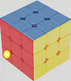
In this post I have explained how to make simple yet fascinating cube light circuits, in which LEDs are connected inside a plastic cube to produce interesting illuminating effects.
All the designs presented below are very simple to build and do not involve any complex microcontroller or Arduino coding.
Why a Cube
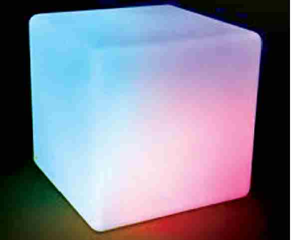
Because cube lights look very attractive compared to other LED set ups. A cube as we know is a square box which has a visible length, breadth, height, and depth, meaning a cube is a perfect unit which can be used for exhibiting a specific parameter through an interesting 3 dimensional mode.
When LEDs are fitted across the walls of a cubical box, and illuminated with specific patterns, we are able to witness fascinating work of lightning, which can be attractive enough to catch the attention of any individual viewing it.
In the cube light project, we will fit one LED on each block of the cube, and illuminate them one after the other in sequence, so that all the blocks start illuminating one by one until the whole cube is illuminated.
The pattern can be sub divided into other variants, for example the delay timers can be made random, so that each block illuminates randomly imitating the house lights of a building apartments switching ON at night randomly.
In another pattern, the delay patterns could be triggered from two ends so that blocks start illuminating from two ends and finally meet at the center to illuminate the whole cube.
Using a Delay ON Timer
We have already studied a simple delay timer in one of our earlier posts, which is shown below:
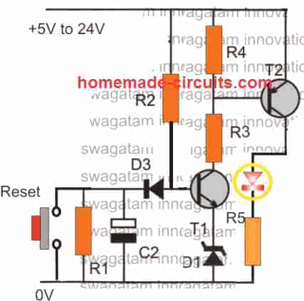
Parts List
- R1 = 47k
- R2 = 100k
- R3, R4 = 10k
- R5 = 1k
- D1 = 3V zener
- D3 = 1N4148
- T1 = BC547
- T2 = BC557
- C2 = 100uF/25V
The idea is very simple, when power is switched, T1 is unable to conduct due to the presence of C2. At power switch ON, C2 grounds the T1 base voltage via R2 D3, and slowly begins charging.
During this time T2 also remains switched OFF, since it is unable to get the required base bias through T1 collector.
As C2 charges, the voltage across it rises slowly, until it reaches a value which is sufficiently high than the combined forward voltages of D3, D1, and T1 (base/emitter drop), which is equal to around 4.2V.
Once this happens T1 now conducts along with T2, and the LED switches ON.
So the delay for the LED to switch ON is determined by the values of R2, C2, D1, D3.
Creating a Sequential LED Lighting
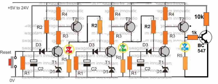
It is easy to cascade many of these timer modules to create a sequential LED ON effect, which can be then implemented for illuminating our cube lights. The design for 3 cascaded sequential LED delay stages can be seen in the following diagram.
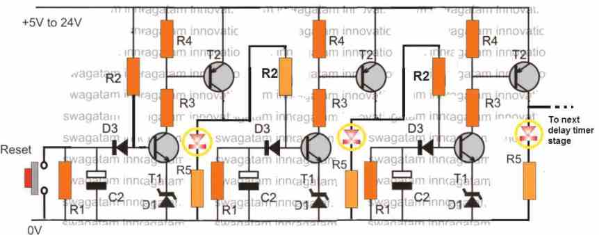
You may need a total of 25 such stages in all to create the intended sequential cube LED lighting as shown in the GIF image above.
If you want to make it quicker, then you can reduce the number of stage to 12, and add two LED in series in each module to cover two blocks at a time in the cube.
Alternatively, you can use 3 such stages, and connect 8 LEDs from each row of the cube to each delay timer, in sequence to create a rising skyscraper effect.
However, if you want to use all the specified 25 stages and want to make it faster or slower, you can do it by selecting lower or higher values for the capacitor C2 appropriately.
How it Works
When the first LED illuminates after a set delay, the collector of T2, provides the charging voltage to the C2 of the next delay timer stage, which causes the second LED to light up after a predetermined delay. Once the second LED lights, the collector of the relevant T2 feeds the next subsequent delay stage to light up the 3rd LED after the set delay...and the system continues to illuminate the cube LEDs with a delayed sequence, one after the other until the whole cube is illuminated.
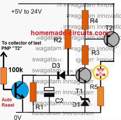
Adding an Auto-Reset
The cube LED cascaded design shown above has a manual resetting function, to add an auto resetting feature, you can replace the reset switch with a NPN transistor or a BC547, and connect its base to the collector of the last T2 through a feedback link, as shown in the following diagram:
Reverse LED chasing
Adding a 10k resistor in series with the collector of the blue transistor will cause sequence operate in slow reverse direction, meaning now all the illuminated LEDs will start shutting off slowly, one after the other, until the last LED is shut off, then the LED will again start illuminating in the forward direction sequentially, and the cycle will keep repeating.
RED, GREEN, BLUE, (RGB) Cube Light
If you have a white cube like box, you can convert it into an interesting RGB color changing cube light circuit, as described below:
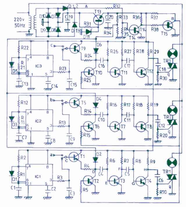
The complete diagram can be witnessed in the following image
As you can it is same circuit as before, but with only 3 delay timer stages. The 3 stages are equipped with the respective RGB LED lights, which illuminate in sequence and then shut off one by one in sequence, producing the intended slow RGB color changing illumination through the cube walls.
All the red, green, blue lights can be 1 watt 300 mA LED lamps.


Comments
Thanks, this was helpful. When creating cube light circuit, are the LED lights to be connected in series or parallel?
Thanks, It should be connected as explained in the article.
OK, thanks
Hi Swagatam,
You suggested the above circuit for my varying beeper project. I want the beeper to produce a short beep once and then be silent until the next delay period has finished. The above circuit was designed for LEDs and once each LED lights, they stay lit until reset. If I replace the three LEDs with one beeper with inline diodes and inline capacitors to limit the beep length, will that work?
Hi Norman, yes that’s right, you can attach the following diode capacitor network at the collectors of T2, and check the response.
the resistors can be 22k each, diodes can be 1N4007, and the capacitor values will need to experimented to get the desired delay.
Thanks so much Engineer. Please, from the circuit diagrams above, what does the circled diode signifies?
The circled diodes are the LEDs.