In this post I have explained an innovative brake light circuit using speed detection of the vehicle which could be a motorcycle. The circuit implements an advanced brake light switch ON ensuring a much safer riding experience for the user. The idea was requested by Mr. Rayan.
Circuit Objectives and Requirements
- I have an idea, usually brake lights of a motorcycle light up only when brakes are applied. But usually the motorcycle speed is reduced by changing down the gears.. so can u make a circuit in such a way that the brake lights light up depending on the speed reduced in the engine, even though the brakes are applied or not.
- In motorcycle .. I wanna install a automatic headlight. Automatic headlight is one which lights wen the engine starts and gets off wen the engine has been made off.
- And also can you make circuit that has automatic dimmer dipper along with automatic headlights..!! And also in the same circuit. I should also have an charging point to charge a cell phone from the battery.
- And I want to make a circuit in which the gears changed in motorcycle should be shown on a screen..! Same as how the left indicator is turned on it shows that the indicator is been made on screen.
- Similarly when I change the gears it should also show me on which gear I'm running my motorcycle.
The Design
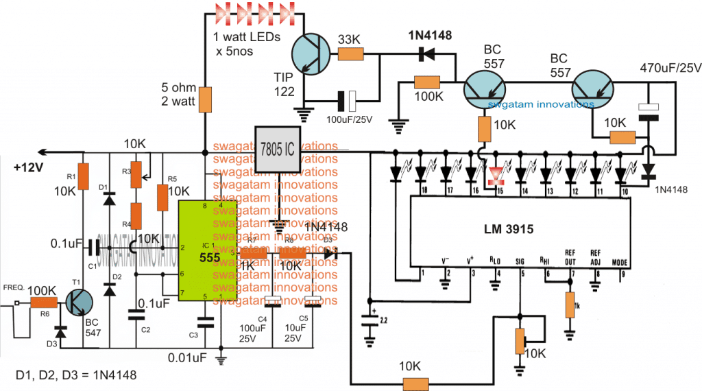
As shown in the above figure, the proposed brake light circuit using speed detection consists of two main stages, viz, the IC 555 tachometer circuit stage and the subsequent LM3915 IC dot mode LED driver circuit stage.
The tachometer circuit stage is configured as an integrator for processing the clock signals from the pick up device of the motorcycle.
The pickup coil translates the engine speed into correspondingly varying clock rate (Hz) which is applied at the base of the BC547 associated with the IC 555 circuit.
These clocks are processed and converted into a exponentially varying voltage across the RC network attached with pin#3 of the IC 555.
The above integrated output is fed to the sensing input of the indicated LM3915 LED dot mode driver stage.
The 10 LEDs connected across the output pins of the LM3915 respond to the exponentially rising and falling voltage levels from the IC 555 output and correspondingly produce a sequentially jumping logic lows across these LEDs, which light up in the identical sequence from left to right, and vice versa.
Since the IC is configured in the dot mode, only one LED lights up at a time while shutting off the preceding ones as the sequence progresses or dances along the line.
This up/down movement of the LEDs represent the speed of the vehicle (or the gear level) and this outcome is exploited by the couple of transistors for switching ON the brake lights through speed detection.
How it Works
The idea here is to detect the speed and switch ON the brake lights only when the speed is detected to be slowing down relatively faster, and ignoring the slower transitions or the delayed changing of gears.
This is important to ensure that the brake lights do not light up on normal lower gear changes intended only to reduce speed, rather than to halt the vehicle at some nearing destination.
This is implemented by the smart use of the two pinouts (arbitrarily selected) and the two respective BC557 transistors attached with the relevant pinouts of the IC LM3915.
The preset at pin#5 of the IC is adjusted such that at relatively higher speeds and gear levels, the last LED in the sequence at pin#10 is switched ON (activated), which correspondingly switches ON the attached right side BC557 transistor.
During this time the left side BC557 shown connected at pin#15 is kept switched OFF (since only pin#10 is ON, rest are switched OFF), therefore the LED driver using the TIP122 is also held switched OFF, and consequently the brake lights are also shut off.
Now, in case the vehicle which could be a motorcycle is intended to be stopped by the rider, and therefore its speed reduced relatively quickly, results in the output of the LM3915 sequencing backwards proportionately and touching down at pin#15.
Since the above sequencing can be expected to happen at a quicker rate, the BC557 at pin#10 is held switched ON by its base RC network even while its base trigger has moved and sequenced across pin#15.
At this instant both the BC557 can be expected to be switched ON, and the LED driver along with the brake lights are also switched ON....the brake lights now light up brightly for some moment of time until the time pin#10 BC557 is able to retain its base capacitor charge level to the optimal switching point.


Comments
A clever design. I would disagree with this part though:
“This is important to ensure that the brake lights do not light up on normal lower gear changes intended only to reduce speed, rather than to halt the vehicle at some nearing destination.”
This is precisely when this auxiliary brake light should come on. e.g. As you approach a curve and have to slow down, many mc riders just use engine braking rather than using the brakes. Since the rider never activates the brakes, the brake lights never come on. If the rider has a tailgater and/or a driver that is not paying close attention, the rider can easily be rear ended.
This is serious if you are driving a car, but it is life threatening if you are riding a motorcycle.
Thank you for your useful insights. I agree with you.
I will try to figure out how the circuit can be upgraded to enable this important feature.
I would think an inexpensive 3 (or more) axis accelerometer board would solve the problem nicely. Then you wouldn’t have to hack into any of the motorcycle’s circuitry and would be a universal solution for all motorcycles. The speedo functions vary drastically across various motorcycle brands, and the age of the motorcycle. Some have better resolution and some worse. There could also be lag in the system. And of course many older bikes have a mechanical speedo.
It would also dramatically simplify installation. You need 12v when the key is on and a ground, and possibly the wire to the conventional brake light so either the new circuit or the brake lever can activate the aux/fancy brake light.
Thanks for your feedback…An accelerometer would require an Arduino or a microcontroller and additional circuitry for processing the data. Although it can be complex and relatively expensive, it will be accurate and worth installing in motorbikes considering the critical nature of the application.
Hi all,
.
As the purpose, as far as I’m reading it, can be boiled down to: Signal whenever the vehicle decelerate at a certain speed (when the velocity change surpasses a given amount/unit time), no matter vehicle type/ignition system/gear/etc. iow, when an unknown mass decreases velocity how much, in a given time frame.
.
The easiest way, yielding the highest precision (no matter where its used), is an analog output acceleration sensor.
Using the X-axis output (if accelerometer is installed correctly), or summing X, Y and Z axis.
One op-amp (or better a comparator), can control a transistor or two, to trigger the brake relay/transistor and since op-amps and comparators often comes with two devices in an 8-pin chip, the remaining could be setup to fast-flash the brake light, when deceleration surpasses a set amount.
.
Analog output accelerometers are dirt cheap in places like eBay and so is LM393, a dual comparator that is well suited for this task.
.
No concerns over ignition systems or anything, just wire up with power and a wire to the brake light relay 🙂
.
/Søren
The purpose of this circuit isn’t making sense to me. Older motorcycles may have a generator driven light that dims as rpm dies down, but newer motorcycles do not. Also, having brake lights get brighter or dimmer when used is a good way to get yourself killed in bad weather – like fog.
I am lost on the purpose of this circuit.
How is this helpful?
This circuit will not make the brake lights brighter or dimmer, rather will cause them to switch ON fully whenever the vehicle speed decreases to some minimal level, and even before the actual brake lights are initiated. So it will help the other motorist who are following from behind to know that this vehicle is slowing down dangerously and might ultimately stop. Even if the vehicle does not finally apply the brakes, it still gives the other motorists an idea regarding the vehicle slowing down to unpredictable levels.
Hello.
Can I use for car? Where to connect to car?
Thanks.
connect exactly as suggested for motorcycle…try it only if you are an expert in electronics