• Skip to main content
  • Skip to primary sidebar

Homemade Circuit Projects

Need circuit help? Post them in the comments! I've answered over 50,000!

Blog | Categories | About | Contact | Calculators-online
You are here: Home / Lamps and Lights / Blinking 3 LEDs (R,G,B) Sequentially Using Arduino Circuit

Blinking 3 LEDs (R,G,B) Sequentially Using Arduino Circuit

Last Updated on June 23, 2019 by Swagatam 6 Comments

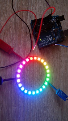
In this post I have explained how to run or blink three LEDs in sequence using Arduino. The post was written and submitted by: Jack Franko

rgb 2

PROGRAM
/* make RGB LEDs to blink in series one by one at interval
of 1000MS */

int R = 12;int G = 11;int B = 10;
void setup(){  pinMode
(R,OUTPUT);  pinMode
(G,OUTPUT);  pinMode
(B,OUTPUT);

}
void loop(){  digitalWrite
(R,HIGH);  delay (1000);  digitalWrite
(R,LOW);  delay (1000);  digitalWrite
(G,HIGH);  delay (1000);  digitalWrite
(G,LOW);  delay (1000);  digitalWrite
(B,HIGH);  delay (1000);  digitalWrite
(B,LOW);  delay (1000);

}

DESCRIPTION

Today, We are  going
to learn to turn on and off  3 LEDs (RED, GREEN, BLUE) one by one at the interval of
1000MS that is one second.
int R = 12;int G = 11;int B = 10;

as we are aware of integer statement we had learned before ,
today we will use integer R,G & B which will be set  on arduino pin no 12, 11 and 10 respectively.
We are using R,G and B for led colors  to set on and off it confidentially to make less complicated and easy to understand what we are doing.
After setting all integers as shown in program above, we will set the main program part which is void setup stated as below

void setup(){  pinMode
(R,OUTPUT);  pinMode
(G,OUTPUT);  pinMode
(B,OUTPUT);

here we are stating the pine mode as output with previously set integer ie. R for pin no 12, G for pin no 11 & B for pin no 10.  After stating arduino pin with pinmode  as output with integer tis time to set our loop for all pins to work with. Here 2nd main function is void loop as stated below.

void loop(){  digitalWrite
(R,HIGH);  delay (1000);  digitalWrite
(R,LOW);  delay (1000);  digitalWrite
(G,HIGH);  delay (1000);  digitalWrite
(G,LOW);  delay (1000);  digitalWrite
(B,HIGH);  delay (1000);  digitalWrite
(B,LOW);  delay (1000);

} Here in statement of loop we are telling arduino to work with pin no 12 which is stated as R in integer and output in void setup. We will tell arduino to set pin no 12 at position “high” which means “ON” and wait for one second which 1000MS in arithmetical language with the help of function “delay” . script stated below will set led to on position and it will wait for 1 second but Arduino will not understand that what to do after waiting for 1 second, this will leads to stay led in on position for long.

  digitalWrite
(R,HIGH);  delay (1000);

so after  one second we must tell arduino to set pin no” 12” ie” R” to position” low”  which is “OFF”.

  digitalWrite
(R,LOW);

the statement stated above will set the led off . If we dint comment to wait for 1 second Arduino will continue to read the loop and turn the LED  to “ON” position frequently .so at this stage we have to comment and state the delay function to tell Arduino that after pin no 12 in “ OFF” wait for 1 second which 1000MS.

  delay (1000);

this is a complete loop for pin no 12 which we had stated for RED LED. This will result to put ON the led and wait for 1 second and OFF the LED and wait for 1 Second. After this we have to set the same loop for GREEN and BLUE LED which is as follows.

  digitalWrite
(G,HIGH);  delay (1000);  digitalWrite
(G,LOW);  delay (1000);  digitalWrite
(B,HIGH);  delay (1000);  digitalWrite
(B,LOW);  delay (1000);

this program will set three LEDs R, G & B to turn “ON” and “OFF” respectively for long time. Her you can program more then 3 LEDs also to turn on and off as you wish. This tutorials are for Newbees to understand the program and to play with Arduino.

You'll also like:

  • 1.  Simple LED Tubelight Circuit
  • 2.  Blinking an LED with Arduino – Complete Tutorial
  • 3.  Arduino Random RGB Light Generator Circuit
  • 4.  Infrared (IR) Controlled LED Emergency Lamp Circuit
  • 5.  LED Strobe Light Circuit with Chasing, Flashing Effects
  • 6.  220V Dual Alternate Lamp Flasher Circuit

About Swagatam

I am an electronics engineer with over 15 years of hands-on experience. I am passionate about inventing, designing electronic circuits and PCBs, and helping hobbyists bring their projects to life. That is why I founded homemade-circuits.com, a website where I share innovative circuit ideas and tutorials. Have a circuit related question? Leave a comment.... I guarantee a reply!

Previous Post: « Tuned Infrared (IR) Detector Circuit
Next Post: Make this Simple Set Reset Circuit using IC 555 »

Reader Interactions

Comments

  1. axel carreon says

    February 27, 2023 at 11:59 pm

    Hi Swagatam,

    Im a newbee on Arduino but willing to learn basics. What type of Arduino kit will i use? For the blinking 3 LED’s.

    Reply
    • Swagatam says

      February 28, 2023 at 9:03 am

      Hi Axel, you can use an Arduino UNO board. For more information on Arduino basics, you can refer to the following post:
      https://www.homemade-circuits.com/learning-basic-arduino-programming-tutorial-for-the-newcomers/

      Reply
  2. Sammy Schutz says

    September 6, 2019 at 12:03 am

    Hi Swagatam,
    I am in need of some help.
    How would you build a circuit to have 3 three LEDs blink in sequence? Could you describe what the actual circuit layout would look like? I am using the NI Elvis Platform.
    Thank you,
    Sammy

    Reply
    • Swagatam says

      September 6, 2019 at 9:27 am

      Hi Sammy,

      By “blinking” do you mean the LEDs should “chase” or “run” in sequence?

      Reply
      • Sammy Schutz says

        September 6, 2019 at 4:52 pm

        I mean that as soon as one turns on it turns off and then the next light turns on and then off and so on. I’m not sure what the proper terminology for that is.

        Reply
        • Swagatam says

          September 7, 2019 at 1:40 pm

          OK you can try the first circuit from this post, with one modification.

          Disconnect IC 4017 IC pin15 from ground and connect it with its pin7

          https://www.homemade-circuits.com/knight-rider-led-chaser-circuit-mains/

          Reply

Need Help? Please Leave a Comment! We value your input—Kindly keep it relevant to the above topic! Cancel reply

Your email address will not be published. Required fields are marked *

Primary Sidebar

Subscribe to New Circuit Ideas

Categories

  • Arduino Projects (87)
  • Audio and Amplifier Projects (132)
  • Automation Projects (17)
  • Automobile Electronics (101)
  • Battery Charger Circuits (82)
  • Datasheets and Components (102)
  • Electronics Theory (143)
  • Free Energy (37)
  • Games and Sports Projects (11)
  • Grid and 3-Phase (19)
  • Health related Projects (25)
  • Home Electrical Circuits (12)
  • Indicator Circuits (14)
  • Inverter Circuits (87)
  • Lamps and Lights (142)
  • Meters and Testers (69)
  • Mini Projects (46)
  • Motor Controller (64)
  • Oscillator Circuits (27)
  • Pets and Pests (15)
  • Power Supply Circuits (108)
  • Remote Control Circuits (50)
  • Security and Alarm (64)
  • Sensors and Detectors (100)
  • Solar Controller Circuits (59)
  • Temperature Controllers (42)
  • Timer and Delay Relay (49)
  • Transmitter Circuits (29)
  • Voltage Control and Protection (37)
  • Water Controller (36)

Calculators

  • Battery Back up Time Calculator
  • Capacitance Reactance Calculator
  • IC 555 Astable Calculator
  • IC 555 Monostable Calculator
  • Inductance Calculator
  • LC Resonance Calculator
  • LM317, LM338, LM396 Calculator
  • Ohm’s Law Calculator
  • Phase Angle Phase Shift Calculator
  • Power Factor (PF) Calculator
  • Reactance Calculator
  • Transistor Astable Calculator
  • Transistor base Resistor Calculator
  • Voltage Divider Calculator
  • Wire Current Calculator
  • Zener Diode Calculator
  • Filter Capacitor Calculator
  • Buck Converter Calculator
  • Boost Converter Calculator
  • Solar Panel, Inverter, Battery Calculator
  • Wire Current Calculator
  • SMPS Transformer Calculator
  • IC SG3525, SG3524 Calculator
  • Inverter LC Filter Calculator

People Also Search

555 Circuits | 741 Circuits | LM324 Circuits | LM338 Circuits | 4017 Circuits | Ultrasonic Projects | SMPS Projects | Christmas Projects | MOSFETs | Radio Circuits | Laser Circuits | PIR Projects |

Recent Comments

  • Swagatam on Best Electronic Circuit Projects
  • TOMMY on Best Electronic Circuit Projects
  • Swagatam on Inverter Circuit with Feedback Control
  • Jerry Adeosun on Inverter Circuit with Feedback Control
  • Swagatam on Contact

Company

  • Privacy Policy
  • Cookie Policy
  • About Me
  • Contact
  • Disclaimer
  • Copyright
  • Videos
  • Sitemap

Social Profiles

  • Twitter
  • YouTube
  • Instagram
  • Pinterest
  • My Facebook-Page
  • Quora
  • Stack Exchange
  • Linkedin
  • © 2025 · Swagatam Innovations