• Skip to main content
  • Skip to primary sidebar

Homemade Circuit Projects

Need circuit help? Post them in the comments! I've answered over 50,000!

Blog | Categories | About | Contact | Calculators-online
You are here: Home / Indicator Circuits / Bird in the Nest Indicator Circuit

Bird in the Nest Indicator Circuit

Last Updated on January 2, 2024 by Swagatam 4 Comments

In this post I have explained a simple infrared based proximity sensor circuit which is implemented to study birds and their behavior, by installing the circuit beside artificially made bird nests. The idea was requested by Mr. Jan Simberg.

Technical Specifications

I hope you have time to read these few lines. First of all thanx for interesting schemas! They are working, too! We are three guys who are studing birds and we have abt 1700 bird nests to check. The bird nest is a small wooden box with a hole in the front.

I'm NOT an electrician but I'm trying to find an inexpencive way to lit a LED outside the nest (only some tens!) when a bird is in. The LED has to flash abt 5 min after every detection of movement.

I can use an rechargeable battery and a solar cell from a garden light - this is OK. I found your "Accurate Infrared Motion Detector or Proximity Detector Circuit" in the Internet and that could be a solution. Can I change the buzzer to a LED with a resistor?

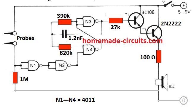
Secondly I found your "Low battery indicator circuit using two transistors only" and that a was a hit. What is the lowest voltage for a rechargeable battery pack 4 times 1,2V = 4,8V? Any ideas how to drop the current consumption? What abt the 5min latch on?

Eddy current and PIR detectors could work but I think they consume current too much. Ultrasound detectors are out of the question - what frequency does a bird hear?

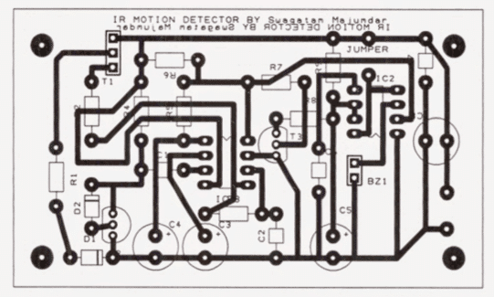
At last, I made a quick PCB layout for your IR detector. Pls delete if too horrible.

Regs,

Jan Simberg

The Design

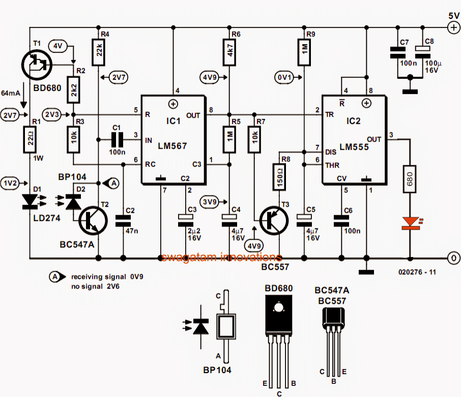
The proposed bird in the nest detector circuit may be understood with the following points:

The IC LM567 is configured in its standard phase locked loop frequency detector mode.

The IR photo diode LD274 is fed with the set frequency from the IC and this photodiode becomes the transmitter device.

Another photodiode BP104 is positioned parallel to the above photodiode such that it can receive the reflected IR rays in the presence of an obstacle (a bird here) within the specified distance in front of them.

The BP104 becomes the receiver IR device of the circuit, and is tuned to respond only to the reflected rays from LD274 and not to any other spurious invasions.

As soon as an obstacle is detected, the BP104 triggers and activates the IC LM567 with a low logic at its output pin8.

However the above triggered low logic will be active only for so long as the intruder is preset in the detection zone.

In order to keep the output sustained for a reasonable period of time, an IC 555 monostable is introduced in conjunction with the IC LM567.

The IC 555 accepts the low signal from pin8 of LM567 and keeps its pin3 high for some predetermined length of time even after the LM567 output is deactivated due to a possible abrupt disappearance of the obstacle.

The period for which pin3 of IC 555 remains ON may be set by suitably adjusting the values of  R9/C5

The transistor T3 restricts and inhibits C5 from charging until pin8 of LM567 is deactivated due to removal of the obstacle.

The above step ensures that the IC 555 output latch ON timing initiates only after the bird has entered the nest, this also ensures that the IC 555 output executes the predetermined time latch only after the pin8 of the IC LM567 has become inactive.

Circuit Diagram

bird in the nest indicator 2

The PCB design for the above circuit, sent by Jan:

bird in the nest indicator 1 1


You'll also like:

  • 1.  Automatic Bathroom/Toilet Engage Indicator Circuit
  • 2.  Simple Water Level Indicator Circuits (with Images)
  • 3.  Simple LED Music Level Indicator Circuit
  • 4.  5 Useful Power Failure Indicator Circuits Explained
  • 5.  Flashing LED Battery Low Indicator Circuit
  • 6.  Car Speed Limit Warning Indicator Circuit

About Swagatam

I am an electronics engineer with over 15 years of hands-on experience. I am passionate about inventing, designing electronic circuits and PCBs, and helping hobbyists bring their projects to life. That is why I founded homemade-circuits.com, a website where I share innovative circuit ideas and tutorials. Have a circuit related question? Leave a comment.... I guarantee a reply!

Previous Post: « Ultraviolet (UV) Sanitizer Circuit for Disinfecting Home Materials
Next Post: How to Connect Car LED Downlight »

Reader Interactions

Comments

  1. Charu Chaubal says

    October 6, 2014 at 12:27 am

    Great Site! Could a similar circuit be created using a 4046 chip instead of the 567? More generally, when would one use the 4046 vs. the 567?

    Reply
    • Swagatam says

      October 6, 2014 at 6:10 am

      thanks, yes 4046 can also be used but 567 is more compact, easily available and less complicated to configure.

      Reply
  2. jideofor5050 says

    February 28, 2014 at 5:57 am

    Please sir, i need a simple transistorised touch sensitive circuit that when touched once it will activate a relay and stay that way until you touch it again before it will deactivate the relay. And again, which of this can perform such function: (Monostable, Bi-stable or Astable multivibrator) ?

    Reply
    • Swagatam says

      March 1, 2014 at 5:19 am

      jideofor, try googling "transistor bistable circuit" you will get plenty of them online.

      Reply

Need Help? Please Leave a Comment! We value your input—Kindly keep it relevant to the above topic! Cancel reply

Your email address will not be published. Required fields are marked *

Primary Sidebar

Subscribe to New Circuit Ideas

Categories

  • Arduino Projects (87)
  • Audio and Amplifier Projects (132)
  • Automation Projects (17)
  • Automobile Electronics (101)
  • Battery Charger Circuits (82)
  • Datasheets and Components (103)
  • Electronics Theory (143)
  • Free Energy (37)
  • Games and Sports Projects (11)
  • Grid and 3-Phase (19)
  • Health related Projects (25)
  • Home Electrical Circuits (12)
  • Indicator Circuits (14)
  • Inverter Circuits (87)
  • Lamps and Lights (142)
  • Meters and Testers (69)
  • Mini Projects (46)
  • Motor Controller (64)
  • Oscillator Circuits (27)
  • Pets and Pests (15)
  • Power Supply Circuits (108)
  • Remote Control Circuits (50)
  • Security and Alarm (64)
  • Sensors and Detectors (101)
  • Solar Controller Circuits (59)
  • Temperature Controllers (42)
  • Timer and Delay Relay (49)
  • Transmitter Circuits (29)
  • Voltage Control and Protection (37)
  • Water Controller (36)

Calculators

  • Battery Back up Time Calculator
  • Capacitance Reactance Calculator
  • IC 555 Astable Calculator
  • IC 555 Monostable Calculator
  • Inductance Calculator
  • LC Resonance Calculator
  • LM317, LM338, LM396 Calculator
  • Ohm’s Law Calculator
  • Phase Angle Phase Shift Calculator
  • Power Factor (PF) Calculator
  • Reactance Calculator
  • Transistor Astable Calculator
  • Transistor base Resistor Calculator
  • Voltage Divider Calculator
  • Wire Current Calculator
  • Zener Diode Calculator
  • Filter Capacitor Calculator
  • Buck Converter Calculator
  • Boost Converter Calculator
  • Solar Panel, Inverter, Battery Calculator
  • Wire Current Calculator
  • SMPS Transformer Calculator
  • IC SG3525, SG3524 Calculator
  • Inverter LC Filter Calculator

People Also Search

555 Circuits | 741 Circuits | LM324 Circuits | LM338 Circuits | 4017 Circuits | Ultrasonic Projects | SMPS Projects | Christmas Projects | MOSFETs | Radio Circuits | Laser Circuits | PIR Projects |

Recent Comments

  • Swagatam on Best Electronic Circuit Projects
  • TOMMY on Best Electronic Circuit Projects
  • Swagatam on Inverter Circuit with Feedback Control
  • Jerry Adeosun on Inverter Circuit with Feedback Control
  • Swagatam on Contact

Company

  • Privacy Policy
  • Cookie Policy
  • About Me
  • Contact
  • Disclaimer
  • Copyright
  • Videos
  • Sitemap

Social Profiles

  • Twitter
  • YouTube
  • Instagram
  • Pinterest
  • My Facebook-Page
  • Quora
  • Stack Exchange
  • Linkedin
  • © 2025 · Swagatam Innovations