In this post I have explained a simple automatic PIR controlled ceiling fan circuit for school college use, which responds and switches ON only in the presence of a human (students) in the classroom. The idea was requested by Mr. Souren Bhattacharya.
Technical Specifications
I am, souren bhattacharya, a high school teacher in west bengal.
To reduce electricity used in my school classroom can you please make a circuit which can switch off/on fans (3/4 ceiling fans) in the classroom as per routine with a facility to manual override.
For example each class has one computer class and one physical education class in a week. we want to switch off ceiling fans when whole class is empty.
The Design
The design will require some kind of human IR sensor to be included, for example a PIR sensor device which looks to be the most efficient and effective for the proposed application.
Incorporating a PIR sensor makes the design pretty simple since most of the complex circuitry is handled within the unit itself.
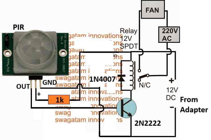
The sensor just needs to be integrated with a triggering stage and a correctly rated power supply as shown in the following diagram.
Circuit Diagram
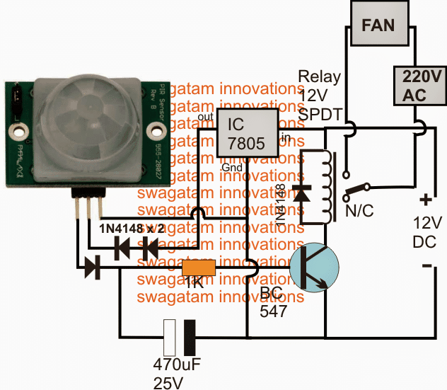
In the given diagram we are able to see a standard preprogrammed PIR module, a 7805 voltage regulator IC stage for supplying the PIR, and a simple 12 V transistor/relay driver stage.
The PIR Module
The PIR module has three terminals, the right one is the ground terminal, center one is the positive +3.3V or +5V, and the left terminal is the responsive output lead of the device.
When the particular assigned (+) and (-) terminals of the PIR device are connected to the specified supply voltages, the device instantly becomes responsive and begins "thinking".
No human presence or motion should be created in front of the unit's lens during this initial switch ON period for about a minute or so, until the device locks ON and puts itself into an alert or a ready stand by position.
The unit now becomes ready and responds to even the slightest human motion or presence in front of its lens by generating a positive supply at its output terminal.
This high at its output terminal persists as long as a human presence is detected within a radial range of around 20 meters in front of the PIR device.
Sensing Human Presence
The output turns into a zero voltage as soon as the human presence moves away or is removed.
The above well defined high/low voltage response at the output lead becomes ideally suited or accessible for a transistor relay driver stage as shown in the diagram.
When the PIR output is high due to the presence of a human (children in classroom), the transistor BC547 base receives the +3.3V out from the relevant lead of the device and quickly switches ON the relay.
The relay in turn switches ON the ceiling fan and the system stays ON as long as the students occupy the premise.
When the students leave and vacate the premise, the PIR instantly switches OFF its output to a zero voltage level.
However, the presence of the 470uF/25V capacitor at the output lead of the PIR prevents the BC547 from getting switched off instantly rather keeps it ON for a few seconds more after the PIR has reverted its output to zero.
After this delay the BC547 also gets deactivated, switching OFF the relay and the ceiling fan or any other desired load whatsoever that may be wired with the relay.
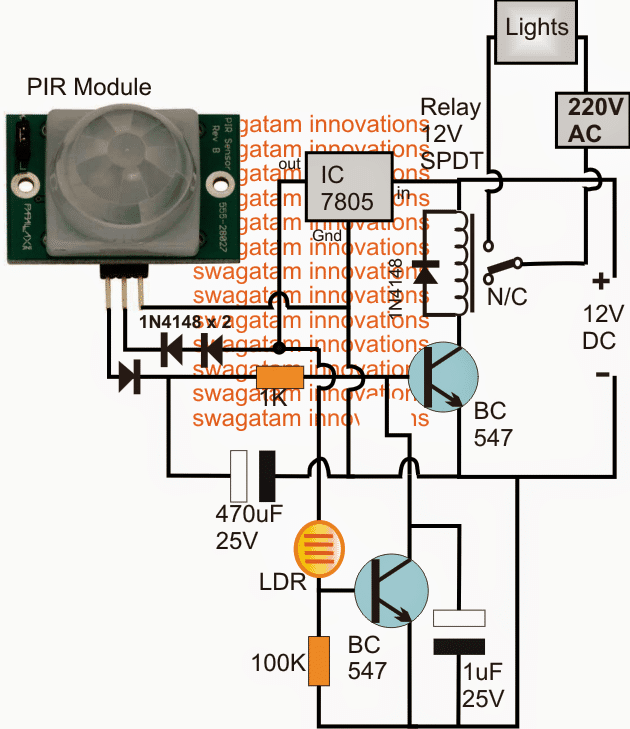
The above circuit may be effectively modified as given below for operating lights, with a feature making sure that it's implemented only during the night time and not during the daytime when ample daylight is accessible. The idea was requested by Mr. Sham.



Questions & Answers
The system uses a PIR sensor to detect motion, triggering both the fan and light to turn on when someone enters the room. Additionally, two manual switches allow the user to override automatic behavior and control the fan or light independently. The fan is controlled using a PWM signal to allow speed control, while the light is toggled via a digital output or a relay. need a schematic for that.
NOTE: Will be Using Labjack U3
You can try the following design:

Can you please guide me in selecting the components specifications if i have to control the total power supply to the room having 4fans and 6LED tubes.
The load you have mentioned will not consume more than 6 amps, so a 10 amp relay should be enough.
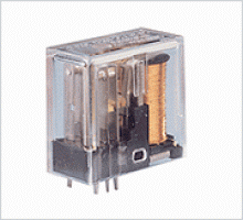
You can use an 12V OEN type relay, as shown below:
You can use the following simplified circuit, it is tested by me:
Thank you for the clear and concise explanation of a simple circuit. I have one question, can the relay be connected to the phase wire coming into the room instead of the fan or light?ay connecting to fan or light, can we connect it to phase wire comming in to the room
You are welcome.
The phase wire has to be in series with the relay contact and the load, the same is true for the neutral wire…The phase, the load, the relay contacts, and the neutral, all should be in series, it doesn’t matter in what sequence they are connected.
Hello Sir I have been following your circuits and ideas with keen interest. Please I have a problem with a similar circuit. I an IR obstacle detector(3 pins – VCC-5v, GND and S-OUT) when it detects an object the output S, goes low. Now i want to drive a motor(5-12V DC) such that when IR detects an object the motor should stop, i used a transistor (TIP41) to rive the motor. I wish I can show my circuit here.
I will be happy if you can help me with a simple circuit to perform this
Hello Kofy, you can upload your image into any online free image hosting side and provide the link here, I will check it, and try to solve it for you..
Is there an alternative for PIR? the PIR we bought is not working.
sorry there’s no effective replacement for a PIR, a PIR mostly will work if configured correctly, make sure the pinouts are joined correctly, for more info you can read the following post:
https://www.homemade-circuits.com/pir-sensor-datasheet-pinout-specification-working/
Hi sir
Can I use two PIR ‘s in this circuit from different locations (different rooms). Because I need it to turn on when there is a human presence in the both rooms.
yes definitely you can do that, by connecting the output pins of the two PIRs through separate 1N4148 diodes and terminating the common cathode ends with the transistor base
Sir thanks for the prompt response.
And Pls suggest me a suitable transformerless circuit to power the above circuit
Naresh,
capacitive power supply is not recommended for this design, you must use a 12V SMPS adapter for operating this circuit.
OK can I use 5.5v cell phone charger and 5v relay?
yes you can try that..
I liked your idea it’s brilliant one but what if I got two fans in The same room and I want them to operate sequentialy
thanks, I am glad you liked it, by sequentially do you mean alternately? in that case you can use the other free contact of the relay and wire it with the other fan….
hi can i know what are the pin configuraion of the sensor ?
as per the orientation shown in the figure it is:
OUT—(+)—GND
sir
can i remove the capaciter from the circuit if i dont want delay in shutting off
can i use this circuit for automatic faucet…tell me if there is any modification
NVD, yes removing the capacitor will cancel the delay effect.
and it can be effectively used for an automatic faucet application…
no mods will be required
Thank u sir
I/p supply y r using 2 * IN4148.
For voltage drop using..
We can use one IN4007…
The output Ampere of IN4148 how much it will produce…
two diodes are for dropping 0.6V + 0.6V = 1.4V from the 5V.
you can use two 1N4007 diodes instead.
ampere consumption will depend on the PIR consumption. 1N4148 rating is 100mA
you can refer to the following article and check how the transistor is configured with the triac, the same can be done with the above circuit
https://www.homemade-circuits.com/2011/12/make-simple-refrigerator-thermostat.html
good day sir
i have made the circuit and its working perfect but its delay period is not so long since the 470 mf capacitor is charging to 3.1 v ( the output volt of the pir module. so inorder to get more delay period how to charge the capicitor to more volt like 12v what modification can i use in the above ckt to get more delay time (i even use 1000 uf still not effective
thaku sir
john
John, you may have to do the following modifications:
remove the relay from the collector of the BC547 and replace it with the 470uF cap.
take a BC557 transistor, connect its base to the collector of BC547 via a 22k resistor….connect its emitter with the positive..and connect the relay across its collector the negative supply line.
goood day sir
i would like to make a pir sensor activating light using 4538 timer ic ,the purpose is the delay period of pir module which i am having is anly about 20 sec
and it turns off before it retriggers.so inorder to get the delay period more can i use a 4538 timer ic . if it posible pls help me how to connect the triggering signal to 4538 ic
thanking you
john
John, you can use a 555 based monostable for the purpose, because using a 4538 could make the configuration unnecessarily a little complex
you can use the following concept with the above PIR ciruit:
https://www.homemade-circuits.com/2014/06/input-trigger-synchronized-monostable.html
Eliminate R3, R4, BC557 from the circuit….and also remove the relay from the above PIR circuit
now simply connect the junction pin#2 and R1 from the 555 circuit with the collector of the BC547 of the PIR circuit
sir, in the above circuit can i use "TWO" pir sensors that results in activating load (light) in two differnt locations. if presence of human in any one of sensor the load should activate how can i insert another "pir" sensor thank you .
Manjunath, yes that can done by configuring the second PIR exactly as the shown PIR in the diagram.
the junction of the 1K and the 470uF gets the input feed from both the PIRs via individual diodes
the supply terminals are joined as per the shown PIR wiring
Good day sir, I am an electrical /electronic engineering student in Nigeria and I have been building most of your circuit ever since and I have to say a very big thanks to you, you are a great man.
I want to build the circuit above but I have a problem with the PIR sensor, I couldn't get the exact model used in the circuit but found another model with five pins/terminals with model number (SV612A-V1.4).
How can I use this model in the circuit above?
Hi Gerald, I am glad to know that you could succeed with many of the circuits from this website.
Please go through the datasheet of the PIR as referred in the previous comment, you should be able to figure out the wiring details, if you still have problems, let me know about it I'll try to help.
Dear sir good day to you,
It works perfect for me. But not accurate. How to adjust Retriggering' option ? (L&H position)Why is this? Can you please tell me?
Hi, you can check out the datasheet of the unit below, and configure the circuit accordingly.
http://www.gme.cz/img/cache/doc/754/295/pir-modul-sb00612a-2-datasheet-6.pdf
Dear sir, good day to you
I tried to build the above circuit but encountered a problem with the PIR sensor.
I couldn't find the the exact model in my country but found another one with five pins with model number (SV612A-V1.4). please sir, how can I use this model in the above circuit?.
Dear Rajkumar,
Please Google "PIR retriggering" and you'll be able to find the the required answer online.
and if you want the circuit to be more sensitive then you may have to employ an opamp for the amplifications, as explained in the following article.
https://www.homemade-circuits.com/2012/10/how-to-understand-and-connect-passive.html
Good day sir. I am an electrical engineering student. I just want to verify if this circuit is applicable for electric stand fan . I am thinking of making this circuit for my research project and i am hoping you could help me with this. Hoping for a response sir.
I'll try to design it if it seems feasible for me….
Yes sir. That would be okay for me sir even if the design is not easy. Can u pls design it sir?
Sansa, do you want the themistor for detecting the room temperature and activating the fan automatically?? that may not be possible with an easy design.
Good day sir. I was so eager to do the circuit but can i request something sir. Can you pls make a circuit also sir that has pir sensor and thermistor as one of the components sir?pls sir. We have our research project and i dont know know how to make tge circuit sir
yes it can be used if its working specification is similar to the shown model.
The type of pir sensor that u use hir sir is not available in our country. i had seen this type of pir sensor revision B 555-28027. Is it ok if i can use it in place of the sb612a-02-001 pir sensor?
You can use any 12V, 5 amp relay, as shown at the end of this article
https://www.homemade-circuits.com/2012/01/how-to-understand-and-use-relay-in.html
Thanks sir. What about the relay sir? What is the maximum and minimum ampere should i use in the ckt so it would work properly?
Sansa, thermistor will not work in place of PIR..if you are planning to make a temp controlled fan then that will be much complex
sir,i am planning to add thermistor in the circuit. will it work? and where can i connect the thermistor if ever sir?what connection is best suitable ?
what kind of pir sensor will i use here sir?
Good day Sansa,
yes you can use it with a stand fan, but please note that the PIR will sense only as long as the people are moving, it will stop sensing if the people are stationery.
Hello sir…very glad to text you…I am electronics student..I need your guidance for my final year project on this topic..can you help me??
Hello Sri, I'll try my best to help, please feel free to ask any related question…
i am unable to find a ckt can you please mail me a ckt for so
Sir,I am a electronics student.. can you help me in my final year project regarding this topic??
it could be your country's internet problem, open the article in any proxy server, you'll be able to see it.
you can connect them in parallel with the same circuit, just make sure the "out" pins are terminated through individual diodes…..
give more info…
Thanks.. Mr. Andrras..
& me also request to …Sir Swagatam to give out a different circuit which is detect by human presence. The title will be "Human presence sensor switch activate" …
Narottam, you can refer to the following recent post for learning regarding my research:
https://www.homemade-circuits.com/2015/08/pir-circuit-for-detecting-static-or.html
Mr Gupta he is absoltely right !! Those comercial PIR's that sell on market can only detect motion either human or not (even a slight leaf movement or passing pet) And by way if you stay still there is no dectection.
Must be something different circuit or different sensor??. Never heard or never see my self,of an oscillating pendulium ????? other than that will take too much space.
But sir…if I do this then also I think will be create a problem…like, the switch will be OFF after the PIR time setting (maximum 5 minutes) then again will be ON. i.e. the relay will be continue ON-OFF..ON-OFF and this is not good for an appliance.
…sorry an oscillating barrier might not work, you'll need an oscillating PIR itself…
How can that happen? I did not get your point?…
yes but the oscillation can cause a continuous ON/OFF of the relay which can be corrected by using small delay OFF circuit.
you can utilize the second circuit from the following article:
https://www.homemade-circuits.com/2012/05/simple-delay-timer-circuits-explained.html
remove the push switch and simply join the 1000uF and the 2m2 junction with the output of the oscillating PIR.
also alternatively, instead of an oscillating the PIR, you can use an oscillating barrier just in front of the PIR which will alternately block the PIR detection and keep it triggering in the presence of a human.
the delay timing can be optimized by appropriately selected the 1000uF cap or the 2M2 resistor.
Sir,
please believe me…
I've done this circuit accurately as your advice…and the relay is operate by the sence of human motion. Don't operate by humane prasence.
And after that I had search in google "function of PIR" and I had seen that… PIR is a human motion sensor.
Yes Narottam you are right, PIR sensor internal circuit is designed to detect only motion, although the actual pyroelectric material can sense human body heat, it's sensitivity can be too weak so it might not detect a static human presence correctly.
To convert the above design into a static human detector you may have to mount the PIR on small motor mechanism or a pendulum kind of mechanism, which will cause the PIR module to oscillate very slowly across a distance of about 3 to 4 inches….this might help to transform any conventional PIR to detect even a static human within the specified range.
Sir,
I've done this project..
but, this circuit work only based human motion, i.e. when I'm lie in the room (no movement by me) then the circuit will OFF after the PIR setting time(maximum 5 minutes), and it will ON again when done some movement by me.
But I want to that circuit which will not OFF when I don't move( like lie in the room) .
plzz help me…
(I'm very poor in English please try to understand that I want to say..)
Narottam, that's not correct, the PIR will keep responding and remain switched ON as long as a human is present within the range of its detection.
If you move away from the range or if you stand somewhere out of its detection zone it won't be able to detect your presence…so make sure the PIR is able to "see" you, meaning keep the PIR in such a way that its angle of detection is maximum and optimal…..
Thank you sir..
I've done this project.
Thnq..sir…For post this circuit.
& I request you to post a circuit of "Wireless mobile charger" plzz sir..
thanks Narottam,
a wireless charger circuit can be a difficult project, if I succeed in cracking it will surely publish it for you!
by the way I have one related circuit which you can refer to
https://www.homemade-circuits.com/2012/01/how-to-make-inductive-li-ion-battery.html
Can we use transformerless to drop down from 220v to 12v dc (max 2W) without using ac/dc adaptor as this will add more money to be spent??
yes, you can the try the following circuit for implementing it:
https://www.homemade-circuits.com/2015/05/zero-crossing-controlled-surge-free.html
I would like to mention one thing. When i connect adapter to relay terminal directly and switch on the supply i could hear only humming noise from relay. That's the reason i chose to add a 100uF cap across the source. When i connected cap, relay was making clicking sound.
No problem sham, there's no short-cut to learning:) ….keep it up
Hi Swagatam,
Yes the adapter was faulty. The supplier mentioned it was current controlled and voltage varies on back inductance. The cap does NOT heat up with other adapter.
It was expensive lesson for me,since i blew up PIR module and couple of ckts i had made. Next time i will cross check the voltages before proceeding.:-)
Plz excuse me for bothering you.
that proves that your adapter is faulty…
I tried with cap before diode. No use, cap still getting veru hot. This time i did not allow to blow up.
Yes, it was reading 26V before blowing up. I was reading the value with supply on.
Am confused now. Why the hell does the cap getting hot. I checked the relay resistance, it is 400 ohms. 4148 is connected across relay. 10uF 25V is connected across relay. I know its simple ckt. With PIR the relay switches few times and after few seconds boom!
Here i would like to know one thing, why my relay is not switching when the 12 v adopter is made contact with relay?
a capacitor will explode only if the fed voltage across it is much higher than its rated value, or if it's connected with the wrong polarity, there cannot be any other reason for a capacitor to explode.
buy another adapter from a different shop and check the results.
Adapter o/p is 12.64 V. I tried connecting a diode between o/p of adapter and cap with 25v rating. It again blew up one more time. I will try connecting cap to adpt terminals directly, i,e before diode and check rather than the relay terminal.
you said it was 26V ?
Hi Swagatam,
Few days back i purchased 12V AC-DC adaptor. Using this i was not able to trigger on the relay. So i connected a 100uF cap across the +ve of relay and other end to GND to remove AC ripples which could have leaked along with DC. This setup was able to trigger the relay. The same i used in simple motion sensor ckt without ldr. Removed 10uF across DC side of relay and connected 100uF to +ve of relay and gnd . PIR was NOT connected(luckily). When i applied 12V, in short time the 100uF exploded while checking the voltage across the cap. It was reading around 26V at that time. I know i have done something wrong. Plz help me in getting this ckt working.
..at 26V your 12V relay will become hot and get damaged soon….
….if it's showing 26v then throw away the adapter, it's a bad quality adapter and very dangerous….if it's rated at 12V then it must show 12V under any cost.
Hi sham, connect the capacitor across the adapter output supply terminals, and make sure that the capacitor rating is much higher than the adapter supply voltage….do this by first confirming the adapter voltage through a multimeter.
Hi Swagatam,
Something went wrong. I purchased 12v AC-DC adaptor. But it was not turning on the relay coil. I could hear humming noise from relay, So i connected 100uF cap across + ve of relay coil and -ve of cap to supply Gnd. It worked for few seconds and later the capacitor exploded. If cap is not connected, relay will not switch on… How to rectify this problem? plz help me.
Yes, Perfect. Its working as desired.
Thanks again Swagatam.
that's great sham….thanks for sharing the result
OK. I got some suggestion from your other article.
https://www.homemade-circuits.com/2011/12/super-simple-light-activated-switch.html
I will try this and update you.
Sham.
OK!
And btw i am using 100k pot at the base of LDR 547.
…a fixed resistor will also do, a pot may not be required because setting the precise time of operation is not so important.
Swagatam,
I noticed that at some point of light intensity, the relay toggles continuously. I have placed the LDR on the other side of the light source. As the daylight fades off the relay started to toggle. Looks like it is not getting latched. How to fix this defect?
I have used 4.7uf across CE of LDR ckt and 100uf from BE of PIR ckt. Since i did not have 1uf and 470uf cap.
Hi Sham, the light from the PIR lamp should not be allowed to fall on the LDR, otherwise it'll malfunction.
also for a stable response you can try connecting a 10uF/25V capacitor directly across the relay coil
Hi Swagatam,
I could not get back early. Please excuse me.
Tested the circuit today. Its working perfectly well. Once again hats off to you and thank you so much.
Hi Sham, that's great, congrats to you on that. I am glad the circuit worked as intended.
Ho very nice. Sure will check tomorrow and inform u. Thanks a lot Swagatam.
you are welcome sham…
Hi Swagatam,
I have tried the above circuit for my kitchen light. It is working perfectly and a great way conserve energy. My kitchen has sufficient daylight during day time so i dont need pir to switch on the light during day time. I need it only during absence of daylight. How to get this done by using LDR in the above circuit?
I have seen your other articles on PIR but it seems to be complicate for me with dual relays and 555 timer. Please show me a simple way to do this.
Thanks,
Sham.
Hi Sham, it's been updated, you can check it out
Thanks Swagatam. Looking forward to it.
Hi Sham, glad to know that the circuit is serving the purpose for you.
I'll upgrade the diagram as per your requirement, and post it soon in the above….please keep in touch.
sir i had build the circuit as shown in diagram and connected light instead of fan and it seems to be not working properly, means if i close the sensor with paper or if nobody present in an range of sensor also the light glows, and while glowing if i went near the light will switches off for few seconds and then glows agalin by making small tik sound . what it means and i was not sure about connecting wire to relay.
i had connected 220 v one wire to nc and and another wire to light and then another wire of light to relays " com" NO of relay has been left without any connection
where the mistake has been occured please suggest me sir,
sorry for my bad english
sure
He connected the relay wrong. He should have connected it to the n/o instead of n/c.
Thanks Manjunath, in the article the PIR is assumed to generate a high pulse on detection of a subject, so the shown connections of the load to the relay is correct, it's across the N/O point….N/C is open
sir, this project also succeded with your guidence. thanks a lot.
but as shown in diagram and reffering to relay topic, i had confused that wheather relay load has to connect to "NC or NO"
but my circuit working .SIR this just to clarify, thanks
As far as I know, HC-SR501 sensor has its Vcc on the left and its control signal pin is its centre pin. If you have connected it correctly, it is not an issue but if you didn't, then you have to interchange the connections between Vcc and signal pin ACCORDING TO CIRCUIT DIAGRAM ABOVE.
If still it does not work, try replacing the transistor as you told that you even tried using a new pir sensor in one of your above comments.
Also recheck the connections that you've made and correct them (if any).
Above steps might solve your problem. Even after following above steps, if your cicuit does not work, try troubleshooting the circuit according to the instructions given by our senior, Swagatam sir.
sir i had used and tested " robodo hc-sr501" in this one is having trigger i think.
thank you
Please let me know the model of the PIR sensor that you've used, so that I could help you further in this regard.
The transistor base LED and the relay LED should light up together in the presence of a human in the zone and shut off permanently in the absence of a a human being
If the LEDs are lighting up with nobody around then there could be something wrong with your PIR device.
sir, sorry to disturb you that i had connected new pir sensor but it was working as before it had. in this comment section interested peoples who suceeded in this project please help me as i am not to disturb this comment section.
was this an right swagatham sir , my mail id
manjujain06@gmail.com
The transistor base LED and the relay LED should light up together in the presence of a human in the zone and shut off permanently in the absence of a a human being
If the LEDs are lighting up with nobody around then there could be something wrong with your PIR device.
SIR, i had made above test by connecting led to transistor base, and another led to relay coil with 1k resistor . both led responce to sensor but led connected to transisitor was too low bright.(was any mistake in this stage) when i switch on both circuit and relay load , even though if no body present in front of sensor it goes on running,and if i move in front of sensor it switch off the load for few seconds and then goes on glowing. please slove this
thanking you
Manjunath, cut the link between the transistor base and the 1k resistor and then connect the longer lead of the LED with the 1K and the shorter lead with the base of the transistor
sir please can you discribe the method of connecting an LED in series with the transistor base resistor to check th faulty stage, or any site address reguarding this . thank you for your cooperation.
manjunath, please do the steps which I mentioned in the previous comment, this is only way you'd be able to troubleshoot the circuit.
pls do it and check the results
sir i had made new circuit of the same above, because of that i cant find the faulty stage. as i am an new to electronics but this was also the same as above so i dicided to send the real picture of my circuit made if you agree. i was so intersted that i dont want to leave this thanks
please check it in the present set up that you have made, or alternatively you can connect an LED in series with the transistor base resistor, if this LED toggles as per the specs, but the relay doesn't then the fault could be in the transistor….for more info you can connect another LED parallel with the relay coil with a series 1k resistor…
check response from all these LEDs, it will help you to pin point the issue.
sir, i had tested pir sensor with both buzzer and led. it was working properly,
then what may be the problem, please help me to correct the circuit . thanks
Manjunath, you can first confirm the working of the PIR sensor separately by connecting an LED across its out and ground pins, while doing this you can keep the relay disconnected from the transistor.
check how the LED responds in the presence or absence of a human body, this will confirm whether the fault is in the PIR or the transistor driver stage.
sir can know the connections of relay 12v spdt in the diagram clearly , that i was new to electronics
manjunath,
the diode can be a 1N4007
relay coil does not have a polarity, so you can simply connect it anyway round across the shown points.
an AC load will never have a polarity, so here too the shown load (fan) may be connected anyway round across the indicated locations
sir I had gone through above link but I have some doubts please solve it sure I will success in this circuit
1) which diod( number of diod) has connected from pir output
2) wheather both side of relay coil are same ( output and input) mean which side of coil is connected to collecter bc 547 and which side of coil to 7805
ground.
3) As in diagram first wire of 220v is connected to realy n/c and that 220v wire ic connected to fan and where to connect other wire of fan to
manjunath please go through the following article for more info:
https://www.homemade-circuits.com/2012/01/how-to-understand-and-use-relay-in.html
sir what should i use as a 12v dc supply… should i design a rectifier circuit separately?…. or using a 12v battery could be a better option?… please guide..
Thanks
Ashish, the 12V could be from a ready made 12V AC/DC adapter unit or any similar power supply.
What will happen if I use 7812 for output of 12v when input of 12vDC instead of 7805 as +5v regulator ?
PIR device will burn ?
Please clear my concept.
if your PIR is specified to work with 5V then surely it will burn.
Sir, the problem I am facing after making the sensor is that .. If I have set the delay timing for 30sec.. And i am sitting in that area ideally i.e. there is no physical movement it would get automatically turn off after the delay timing.. Can u plzz suggest me how to rectify this problem of mine..
Ankur, PIR devices are designed for sensing IR from our bodies not for sensing motion….so if it's not sensing your presence then may be you are not in the range of the device or there's some fault in the system components.
Sir from where I will get PIR sensor and is it costly
yes it will be a bit costly, inquire with your local electronic retailer, he'll know better.
If I used the sensor for a cfl light or tube light, when I entire the dark room then it worked properly?
yes it will work.
When I needs to change the speed of the fan then what happens otherwise it's controlled by human manually?
speed control has no connection with the above circuit, it'll need to be controlled through a series regulator as usual
how many circuits are required for controlling 3/4 fans in a 350 sq/ft class room.?? is the sensor is available in kolkata?/
A single unit would take care of each room comfortably, preferably it could be positioned on the center of the ceiling in order to get a radial view of the classroom.
All the fans could be controlled through the single relay for getting a simultaneous ON/OFF toggling.
PIR sensors have become too common nowadays, so it should be easily available in Kolkata too.
if any animal comes it will get on? i mean cat or dog? if human motion is not there will it remain on position?
yes it'll detect all warm blooded living beings..
with nobody in the range the unit will stay shut off…and get activated when the same is detected