In this post I will comprehensively discuss 10 different types of active filter circuits which can be used for filtering music and audio with the desired levels of bass and treble effects. We also learn about their working, types, characteristics, and practical applications circuits.
Contributed By: Ken Madison
In audio signal processing circuits, filters are used to eliminate undesired frequencies while allowing only the required frequencies. There are audio high-pass, low-pass, bandpass, and notch or band-rejection filters, just like we have filters for many other frequencies. Passive, resistor-capacitor (RC) filters are among the most basic audio filters.
RC Filters
The design for a basic L-section resistor-input RC passive filter is shown in Figure 1-a, in which the capacitor C1 functions like an open circuit at lower frequencies and like a short circuit at higher frequencies.
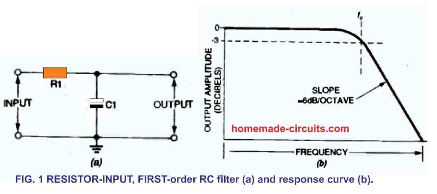
Consequently, this low-pass filter accepts low-frequency signals while rejecting (significantly attenuating) high-frequency signals. At a cutoff frequency (fc), the output of this filter rolls-off by 3 decibels (dB), where:
(1) fc = 1 /(2πRC)
As demonstrated in Fig. 1-b, as frequency increases exceeding the cutoff, frequency rolls-off at a rate of 6 dB/octave (20 dB/decade).
As a result, a 1 kHz low-pass filter cuts a 4 kHz input signal by 12 dB and a 10 kHz signal by 20 dB.
Figure 2-a depicts a second fundamental, passive RC filter, which is an L-section capacitor-input filter. At lower frequency, the capacitor also functions like an open circuit, whereas at high frequencies, it acts like a short circuit. As a result, this high pass filter allows high-frequency signals to travel through while rejecting low-frequency ones.
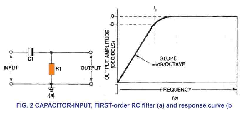
As calculated by the above formula (1) implemented to the low-pass filter in Fig. 1-a, the output of this high-pass filter is 3 dB lower at the cutoff frequency. As the frequency is lowered below this threshold, it rolls off at a 6 dB/octave rate, as illustrated in Fig. 2-b. As a result, a 1 kHz high-pass filter suppresses the signal by 12 dB to 100 Hz.
Active Filters
Basic RC filters cannot be cascaded since their interconnections could create a negative impact on the output. Nevertheless, using feedback circuits with operational amplifiers, these can be efficiently cascaded.
External resistors and capacitors could be used to create active filters built around operational amplifiers, eliminating the use of large inductors. A Butterworth filter circuit diagram is indicated in Figure 3.
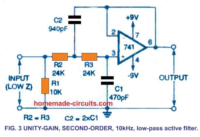
This is a second-order, unity-gain low-pass filter having a cutoff frequency of 10 kHz. In the passband, the Butterworth filter has a significantly flat amplitude response, along with a modest settling time, and a modest overshoot. Above 10 kHz, the output of this circuit rolls off by 12 dB every octave. At 100 kHz, for instance, the output might be 40 dB lower.
The Butterworth filter's cutoff frequency can be calculated using the following formula:
(2) fc = 1 /(2.83πRC)
You can change the settings of the resistors and capacitors in the active filter to change the cutoff frequency. If the value of the resistor or capacitor is known, the variables in formulae (1) or (2) (as applicable) could be adjusted to work out a given cutoff frequency.
The need that one of the capacitor values in the Fig. 3 design be exactly double the value of the other appears to be a small drawback. (Capacitor C2 in Fig. 3 has a value that's two times the value of C1). This restriction usually necessitates the use of nonstandard capacitor values.
Figure 4 depicts a different active low-pass filter. It's a second-order filter featuring a cutoff frequency of 10 kHz that addresses the problem with the circuit in Fig. 3.
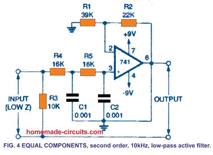
The values of the capacitors R4 and R5 are the same. In both the Figs., the ordinary IC 741 op-amp is used, which uses the resistors R1 and R2, 3 and 4 to offer a voltage gain of 4.1 dB.
These must match the figures used in Fig. 4. Formula (1) may be used to get the cutoff frequency for this "equal components." filter.
Figure 5 illustrates the method of cascading these "equal component" filters to create a fourth-order low-pass filter having a 24 dB/octave rolloff.
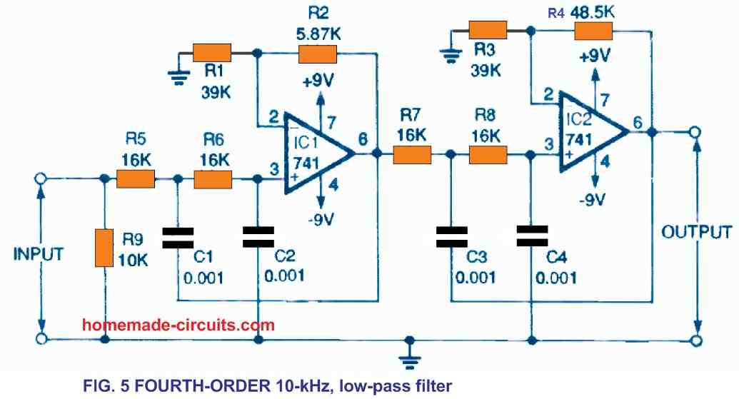
The resistive divider of R1/R2 which determines the gain in this circuit is 39 kilohms divided by 5.87 kilohms, or 6.644. The R3/R4 potential divider is built using 39 kilohms/48.5 kilohms, resulting a value of 0.805. This provides a total voltage gain of 8.3 dB for the circuit.
To get the nonstandard R2 and R4 values, you can hook up a couple of standard 5 percent tolerance resistors in series to match the values indicated. A second-order, 100-Hz, high-pass filter with unity gain is shown in Figure 6.
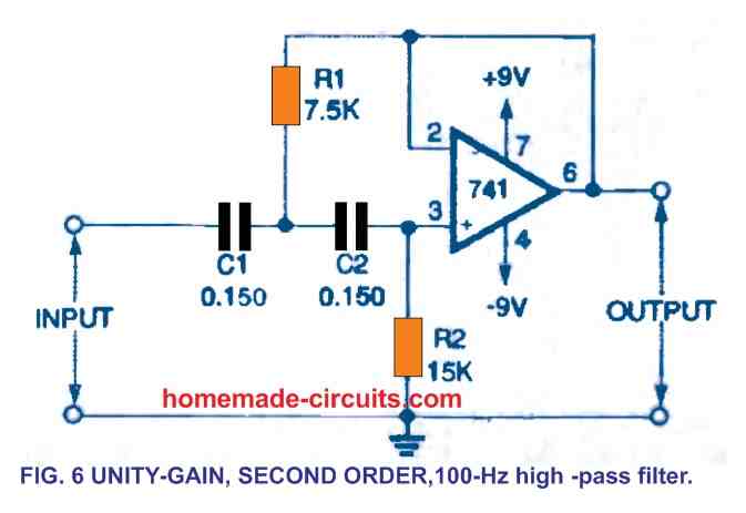
R2 is a resistor with double the resistance of R1.
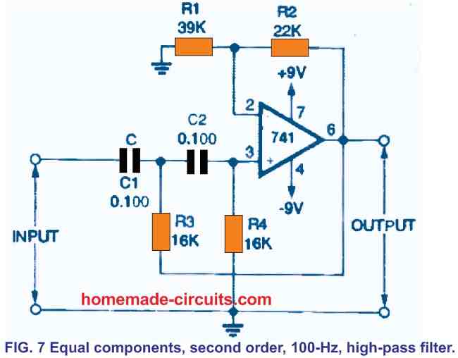
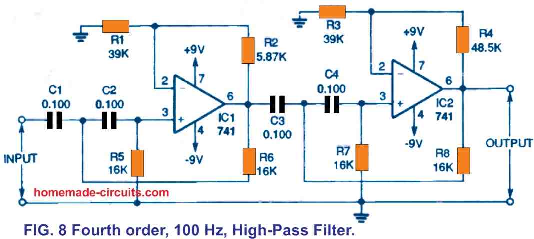
Figure 7 shows a "equal component" variant of the filter, wherein R3 and R4 are the same. A fourth-order high-pass filter is shown in Figure 8. The working frequencies of the filters in Figs. 6 and 7 as well as those in
Figs. 4 and 5 may be changed in the same manner as the working frequencies of the Fig. 2 concept could be changed. You may increase the values of the resistor and capacitor in order to decrease the cutoff frequency, or vice versa.
Figure 9 illustrates the method through which the high-pass filter circuit from Figure 7 and the low-pass filter schematic from Figure 4 could be combined in series to generate a 300-Hz to 3.4-kHz speech band-pass filter (with appropriate part value adjustments).
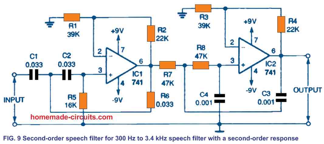
All frequencies that are outside this frequency range are rejected by 12dB/octave. To boost the cutoff frequency from 100 Hz to 300 Hz in the high-pass filter shown in Figure 7, the capacitor values are 1/3rd of the original numbers. We multiply the original resistor values with 2.94 in the low-pass filter of Fig. 4 to decrease the cutoff frequency from 10 kHz to 3.4 kHz.
Adjustable Active Filters
The most customizable active filter is the one having a cross-over frequency that can be readily and completely adjusted across a large range. Three realistic circuit diagrams of second-order variable active filters are shown in Figures 10, 11, and 12.
The Fig. 10 design is a basic version of the Fig. 6 high-pass filter, however its cutoff frequency may be adjusted between 23.5 Hz and 700 Hz by evenly setting the matched potentiometers R3 and R4.
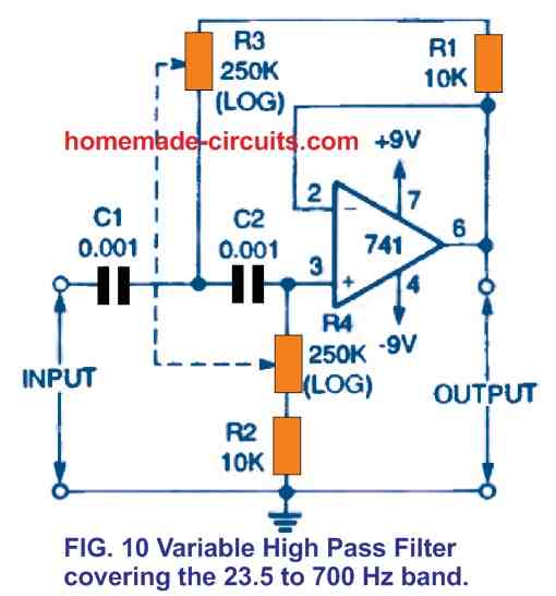
(These could be ganged mechanically.) Because the resistors in the RC networks in this circuit contain equal values (unlike those in Fig. 6), this configuration doesn't really produce one of most flat Butterworth filter characteristic. Nonetheless, it provides excellent signal quality . This filter's "static" version typically has a cutoff frequency of 50 Hz.
The Fig. 11 circuit design is a modified version of the Fig. 3 high-pass filter, although its cutoff frequency is entirely adjustable from 2.2 kHz to 24 kHz through constant adjustment of paired potentiometers R3 and R4. (These, too, could be ganged.) This filter, like the one in Fig. 10, doesn't really exhibit the most flat Butterworth feature.
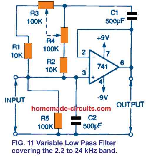
This active filter design is actually an excellent scratch noise removal filter. The cutoff frequency of "fixed" versions of this filter is generally 10 kHz.
Figure 12 depicts the method in which the filters in Figures 10 and 11 could be coupled to produce a flexible, adjustable high-pass/low-pass filter for eliminating rumble and scratch noise from voice audio.
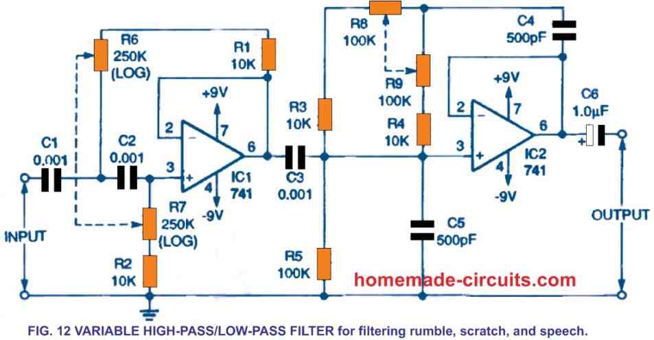
The low-pass and high-pass cutoff frequencies are both completely adjustable.
The high-pass cutoff frequency could be adjusted from 23.5 Hz to 700 Hz by evenly altering the matched (or ganged) potentiometers R6 and R7. R8 and R9 may also change the low-pass frequency between 2.2 kHz and 24 kHz.
Tone Control Circuits
Audio tone control circuits are perhaps the most common adjustable filter circuits. These enable the frequency response of the unit to be adjusted to fulfill specific hearing needs or feelings. They can be also adjusted for acoustic abnormalities in the surroundings.
In the next paragraphs some of the fundamental tone-control principles and circuits would be discussed before considering the practical tone-control circuits.
A basic passive, bass, tone-control network is shown in Figure 13-a. Inside the audio range of 20 to 20,000 Hz, this circuit may be able to enhance or decrease (cut) low frequencies.
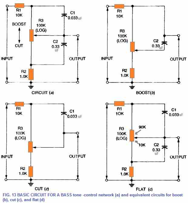
The direction of pot slider rotation to get boost (up) and cut is indicated by the vertical double-ended arrow adjacent to trimmer potentiometer R3 (down).
The corresponding circuits are shown in Figures 13-b to 13-d when potentiometer R3 is adjusted to highest boost, highest cut, and flat, respectively. Once the frequency is set at its minimum bass value, capacitors C1 and C2 are fully open-circuited. As a result, the boost circuit becomes proportional to a 10 kilohm resistor divided by a 101 kilohm resistor, as can be seen in Fig. 13-b.
Only a little amount of bass is attenuated. By comparison, the Fig. 13 -c cut equivalent circuit is equivalent to a 110 kilohm resistor divided by a 1.0 kilohm resistor. Bass signals are attenuated by roughly 40 decibels as a result of this. Figure 13-d illustrates the flat setting of potentiometer R3.
In this set up the resistive element can be seen as 90 kilohms above the slider of the pot and 10 kilohms below it. A 100-kilohm resistor is divided by an 11-kilohm resistor to create the above configuration.
Throughout all frequencies, this circuit generates roughly 20 dB of attenuation. Due to this, the circuit is able to provide a maximum bass boost or reduction of around 20 dB when compared to flat frequencies.
A typical design for a passive treble tone-control configuration is shown in Figure 14-a. Inside the 20 to 20,000 kHz frequency range, the system is able to efficiently amplify or decrease high-audio frequencies. Technically identical circuits are shown in Figures 14-b to 13d during optimum boost, optimum reduction, and during flat operating conditions, respectively.
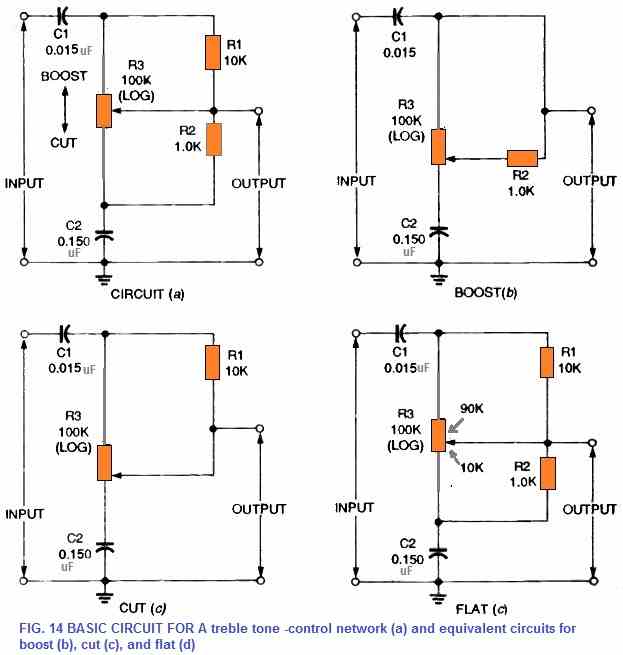
When R3 is moved around the flat position, this circuit provides around 20 dB of signal attenuation and highest possible treble, boost, or reduction values of 20 dB compared to the circuits' flat region performance.
Figure 15 illustrates the method through which the circuits in Figures 13 a and 14 a may be interconnected to provide a comprehensive passive bass and treble tone-control configuration.
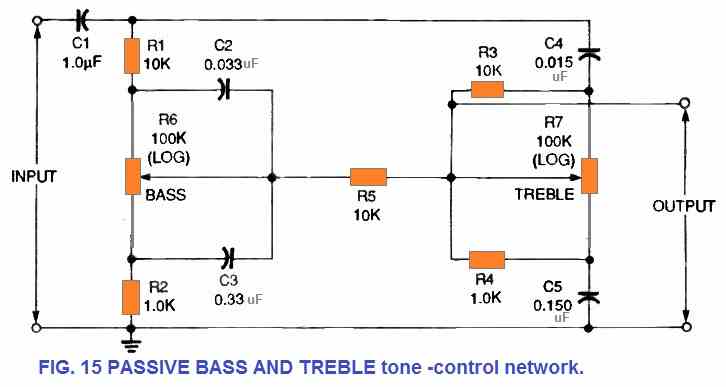
To avoid undesired interactions between the different portions of the circuit, a 10 kilohm resistor R5 has been introduced in the network. The output of this circuit may be fed to the input of a primary power amplifier, while the input could be obtained directly from an amplifier's volume control.


Comments
我想弄一個3階的高通濾波器,主要想用在麥克風的降噪,我看了原理應該是在80Hz需有18dB的衰減,但卻不知線路圖該怎麼畫,請問可以協助嗎
Here’s a simple passive circuit you can try for a 3rd order high pass filter to remove low-frequency hum, rumble, and handling noise below 80 Hz.
https://www.homemade-circuits.com/wp-content/uploads/2025/07/3-order-high-pass-filter.jpg
For figure 12 “adjustable high-pass/low-pass filter ” how important is it that R6/R7 is a logarithmic taper? A250K Dual pots are difficult to find, could the values in the circuit be changed to use a 50K,100K, or 1M dual log instead? Thanks!
You can try using 4nos of 100k pots, 2 in series for the top pot, and 2 in series for the lower pot.
please help me with the complete circuit on how to disgn and implementation of an efficient active noise control system
Can you please provide the specifications of the noise frequency….I will try to figure it out…
Very useful schematics!
I will be very grateful if you send me a link related to schematics about “Tunable CW Audio Filters” (with OP Amps.)
Best regards: George
Thank you George,
I do not have the circuit for “Tunable CW Audio Filters” at the moment, if I find one, will surely let you know.
Design and compare active and passive filters for audio systems. Consider factors like frequency response, phase shift . This is the statement for open ended lab . Please give any idea.
Sorry, I do not have the calculation details for the above filter circuits. You can perhaps check out the following article:
https://www.homemade-circuits.com/design-high-pass-filter-circuit-quickly/
https://www.homemade-circuits.com/phase-shift-oscillators-wien-bridge-buffered-quadrature-bubba/
I have two electrostatic panels; fullrange 35 Hz – 20.000 Hz (height 190 cm) and bought two active subwoofers; second hand. I listen to almost only classical music. The subwoofers are only for lower listening volumes, as the panels deliver good bass at higher volumes. The subwoofers miss a low filter and they work far too high, still at 200-250 Hz. I like to use a filter to cut off the audio signal above 80 Hz. Can you advice me? Passive or active filtering? Thank you!
Sure! I think you can try the last circuit from the following article:
https://www.homemade-circuits.com/make-this-low-pass-filter-circuit-for/
Fantastic website and content. Keep up with the great work!
Thank you!
thanks alot