• Skip to main content
  • Skip to primary sidebar

Homemade Circuit Projects

Need circuit help? Post them in the comments! I've answered over 50,000!

Blog | Categories | About | Contact | Calculators-online
You are here: Home / Datasheets and Components / TIP127 Datasheet [100V, 5 Amp PNP Darlington Transistor]

TIP127 Datasheet [100V, 5 Amp PNP Darlington Transistor]

Last Updated on February 27, 2023 by Swagatam Leave a Comment

The TIP127 is a PNP Darlington transistor commonly used for high-power switching applications. Here is the complete datasheet for this transistor:

Table of Contents
  • Electrical Characteristics:
  • Thermal Characteristics:
  • Pin Configuration:
  • Internal Darlington Configuration
  • How to Switch ON TIP127 Transistor
  • Package Information:
  • Typical Applications:
  • Limitations:
  • Other Features:

Electrical Characteristics:

  • Collector-Emitter Voltage (VCEO): 100V
  • Collector-Base Voltage (VCBO): 100V
  • Emitter-Base Voltage (VEBO): 5V
  • Collector Current (IC): 5A (continuous), 8A (peak)
  • Base Current (IB): 50mA (continuous), 100mA (peak)
  • Power Dissipation (PD): 2W
  • Minimum hFE or DC Current gain: 1000

Thermal Characteristics:

  • Junction Temperature (Tj): -65°C to 150°C
  • Thermal Resistance - Junction to Case (RθJC): 3.125°C/W
  • Thermal Resistance - Junction to Ambient (RθJA): 62.5°C/W

Pin Configuration:

warning message: electricity is dangerous, proceed with caution
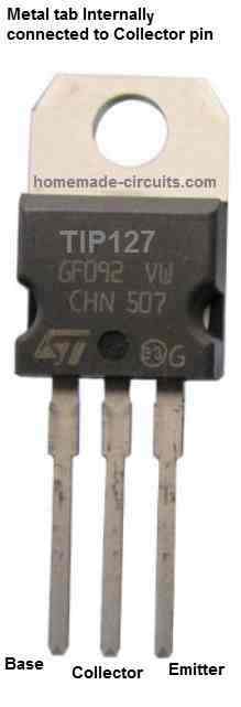
TIP127 pinout details

As shown in the above figure, the TIP127 transistor has three pins: the collector (C), the base (B), and the emitter (E). The pinout configuration is as follows:

  • Pin 1: Base (B)
  • Pin 2: Collector (C)
  • Pin 3: Emitter (E)

Internal Darlington Configuration

The TIP127 is a PNP Darlington transistor which has two PNP transistors configured with each other, as shown in the following diagram:
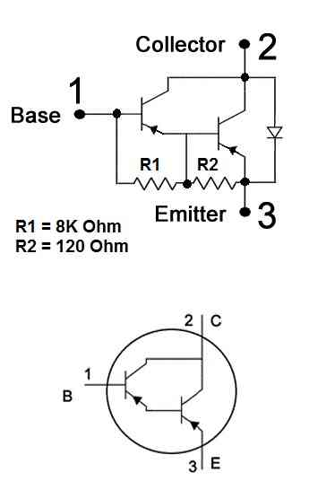
TIP127 internal Darlington configuration

How to Switch ON TIP127 Transistor

Since the TIP127 is a PNP transistor, it can be switched ON by applying a negative potential to it base pin, as shown in the following circuit diagram:
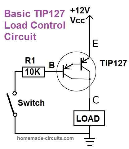
tip127 load control circuit

Package Information:

The TIP127 transistor is available in the TO-220 package, which is a through-hole package with a single mounting hole. The package dimensions are as follows:

  • TO-220 Package: 10.67mm x 15.87mm x 4.83mm

Typical Applications:

The TIP127 transistor is commonly used in high-power switching applications, such as:

  • Power supplies
  • Motor control
  • Lamp dimming
  • Solenoid control
  • Audio amplifiers
  • High-current drivers

Limitations:

  • Maximum Collector Current: 5A (continuous)
  • Maximum Power Dissipation: 2W
  • Maximum Voltage: 100V

Other Features:

  • Darlington Configuration
  • High DC Current Gain (hFE)
  • Low Saturation Voltage (VCEsat)

Note: This information is taken from the TIP127 datasheet published by ON Semiconductor. Actual values may vary based on specific manufacturer and production batch.

You'll also like:

  • 1.  LM195/LM395 Power Transistors Explained [Enhanced Power Transistors with Full Internal Protections]
  • 2.  IC IR2184, IR21844 Half-Bridge Driver Circuit Diagram, Datasheet, Working
  • 3.  High Voltage, High Current Transistor TIP150/TIP151/TIP152 Datasheet
  • 4.  Understanding IC 4043B, IC 4044B CMOS Quad 3-State R/S Latch – Working and Pinouts
  • 5.  IC 4070 Datasheet, Pinout Working, Truth Table, Electrical Characteristics
  • 6.  Arduino LCD KeyPad Shield (SKU: DFR0009) Datasheet

About Swagatam

I am an electronics engineer with over 15 years of hands-on experience. I am passionate about inventing, designing electronic circuits and PCBs, and helping hobbyists bring their projects to life. That is why I founded homemade-circuits.com, a website where I share innovative circuit ideas and tutorials. Have a circuit related question? Leave a comment.... I guarantee a reply!

Previous Post: « IC 4027 Datasheet, Pinout Working, Application
Next Post: IRF510 Datasheet [100V, 5.6 Amp, N-Channel MOSFET] »

Reader Interactions

Need Help? Please Leave a Comment! We value your input—Kindly keep it relevant to the above topic! Cancel reply

Your email address will not be published. Required fields are marked *

Primary Sidebar

Subscribe to New Circuit Ideas

Categories

  • Arduino Projects (87)
  • Audio and Amplifier Projects (132)
  • Automation Projects (17)
  • Automobile Electronics (101)
  • Battery Charger Circuits (83)
  • Datasheets and Components (104)
  • Electronics Theory (143)
  • Free Energy (37)
  • Games and Sports Projects (11)
  • Grid and 3-Phase (19)
  • Health related Projects (25)
  • Home Electrical Circuits (12)
  • Indicator Circuits (14)
  • Inverter Circuits (87)
  • Lamps and Lights (142)
  • Meters and Testers (69)
  • Mini Projects (46)
  • Motor Controller (64)
  • Oscillator Circuits (27)
  • Pets and Pests (15)
  • Power Supply Circuits (108)
  • Remote Control Circuits (50)
  • Security and Alarm (64)
  • Sensors and Detectors (101)
  • Solar Controller Circuits (59)
  • Temperature Controllers (42)
  • Timer and Delay Relay (49)
  • Transmitter Circuits (29)
  • Voltage Control and Protection (37)
  • Water Controller (36)

Calculators

  • Battery Back up Time Calculator
  • Capacitance Reactance Calculator
  • IC 555 Astable Calculator
  • IC 555 Monostable Calculator
  • Inductance Calculator
  • LC Resonance Calculator
  • LM317, LM338, LM396 Calculator
  • Ohm’s Law Calculator
  • Phase Angle Phase Shift Calculator
  • Power Factor (PF) Calculator
  • Reactance Calculator
  • Transistor Astable Calculator
  • Transistor base Resistor Calculator
  • Voltage Divider Calculator
  • Wire Current Calculator
  • Zener Diode Calculator
  • Filter Capacitor Calculator
  • Buck Converter Calculator
  • Boost Converter Calculator
  • Solar Panel, Inverter, Battery Calculator
  • Wire Current Calculator
  • SMPS Transformer Calculator
  • IC SG3525, SG3524 Calculator
  • Inverter LC Filter Calculator

People Also Search

555 Circuits | 741 Circuits | LM324 Circuits | LM338 Circuits | 4017 Circuits | Ultrasonic Projects | SMPS Projects | Christmas Projects | MOSFETs | Radio Circuits | Laser Circuits | PIR Projects |

Recent Comments

  • Swagatam on 10 LED Tachometer Circuit Diagram
  • Swagatam on How Shunt Regulator TL431 Works, Datasheet, Application
  • Göran on 10 LED Tachometer Circuit Diagram
  • SA on How Shunt Regulator TL431 Works, Datasheet, Application
  • Swagatam on Adjustable 0-100V 50 Amp SMPS Circuit

Company

  • Privacy Policy
  • Cookie Policy
  • About Me
  • Contact
  • Disclaimer
  • Copyright
  • Videos
  • Sitemap

Social Profiles

  • Twitter
  • YouTube
  • Instagram
  • Pinterest
  • My Facebook-Page
  • Quora
  • Stack Exchange
  • Linkedin
  • © 2025 · Swagatam Innovations